Showing posts with label Door/Window Assembly. Show all posts

November 26, 2010

ACA 2011 - Opening Location Changes - Part 4

First Post in Series: ACA 2011 - Opening Location Changes - Part 1
Previous Post in Series: ACA 2011 - Opening Location Changes - Part 3

To wrap up this series on opening location changes in AutoCAD® Architecture 2011, we will look at the ribbon tools that have been provided to make using them somewhat less tedious. Several choices have been combined into one ribbon tool, reducing the number of steps needed when working "manually", as presented in the previous articles.

These tools are located on the Wall contextual ribbon tab, on the General panel, so in order to access them, you will need to select a Wall. The Door and Window tools are now split buttons, and if you click on the lower half of the tool (the part with the arrow icon), you will get a list of tools from which to choose. For Doors, these tools are Door (DOORADD command), Offset from Grid Line (DOORADD GRID YES POSITION OFFSET command), Center between Grid Lines (DOORADD GRID YES POSITION CENTER command), Evenly between Grid Lines (DOORADD GRID YES MULTIPLE command), Evenly between walls (DOORADD GRID NO MULTIPLE command) and Entire Wall (DOORADD WIDTH MAXIMIZE command).The same options are available for Windows (substitute the WINDOWADD command for the DOORADD command).Since Openings and Door/Window Assemblies do not offer the relative to grid line or multiple options, there are no additional choices on the Opening-Door/Window Assembly tool.
One thing to keep in mind is that when you choose one of the Door or Window tools from the flyout other than the "plain" Door (DOORADD) or Window (WINDOWADD) tool, some of the options associated with that tool will become your new default options. The Relative to grid and Position properties will retain the selected option. The Multiple insert property will maintain a default value of No.

I personally do not see much use for the Entire Wall tools, particularly with respect to Doors, but if you need to fill an entire Wall segment with a Door or Window, the option is there. I would be more likely to want to use the Entire Wall option with a Door/Window Assembly, but that is not an option for Door/Window Assemblies.

November 12, 2010

ACA 2011 - Opening Location Changes - Part 3

First Post in Series: ACA 2011 - Opening Location Changes - Part 1
Previous Post in Series: ACA 2011 - Opening Location Changes - Part 2

Another new feature is the ability to place multiple openings at once. As with the relative to grid feature, the multiple openings feature only applies to Doors and Windows. The openings can either be spaced evenly on the selected segment or centered on the segment with a fixed offset between the openings. Relative to grid can be set to either No (use Wall Ends or intersecting Walls) or Yes (use intersection Grid lines) to determine the Wall segment over which the multiple openings will be placed. In the images here, a Window object will be placed with Relative to grid set to Yes.

The sequence of picks and settings is somewhat fussy, so pay close attention to the following. If you prefer, you can also read the Command: line prompts and set the property values there using the command options.
  1. Start WindowAdd command by whatever means you normally do (eg, tool palette tool).
  2. Select a Wall in the drawing.
  3. On the Properties palette, on the Design tab, in the Dimensions category, set the desired Width and Height (or choose the desired Standard size).
  4. In the Location category, set Relative to grid to the desired value. The value of the Position property does not matter.
  5. Set the Multiple insert property to Yes. Notice that the Command line prompt now asks you to select a Wall segment. Yes, you will need to select a Wall again, but this time you need to pick the exact segment you want. As you hover over a Wall, notice the solid red line that shows up, in addition to the Wall highlight (assuming you have highlighting while selecting turned on).The red line defines the extents of the Wall segment over which the multiple openings will be inserted. When you have the segment you want, select the Wall
  6. You can now set the number of openings to insert, either in the Number to insert property or at the Command: line prompt. The initial default value will be the maximum number of openings that can be fit along the selected segment. For the example here, the default was 6, but I changed it to 3.
  7. In the Location category, choose the desired value for the Spacing property, Equally or Offset.
    • If you choose Equally, then the difference between the segment length and the sum of the Widths of the openings, will be divided into equal segments, at the beginning, between each opening and at the end.
    • If you choose Offset, another property, Offset multiples, appears, allowing you to specify the distance between the openings. The entire array is centered on the segment, so the additional space is divided equally to each side.
  8. Finally, left click in the drawing area to accept the arrangement ghosted on the screen and continue on with the command in progress (WindowAdd in the example). The Multiple insert property will reset to no, so if you want to add another set of multiple openings of the same object, you will need to start the sequence above from Step 3 (Step 5 if the opening size and Relative to grid are to remain the same).
The next installment will look at the ribbon tools that can make using these features less fussy.

Next Post in Series: ACA 2011 - Opening Location Changes - Part 4

October 16, 2010

ACA 2011 - Opening Location Changes - Part 2

First Post in Series: ACA 2011 - Opening Location Changes - Part 1

The first post covered the splitting of the Offset/Center option into separate Offset and Center options when placing a opening (Door, Window, Door/Window Assembly or Opening) object in a Wall, and showed how that worked for a Door, using Wall ends or intersecting Walls to define the Wall segments to which the Offset or Center applies. In this post, we will look at the newly added "Relative to grid" property, which only applies to Doors and Windows.

When set to "No", Walls are used to define the segments, as in previous releases. When set to "Yes",AutoCAD® Architecture will use grid lines that intersect the Wall to determine the Wall Segment over which the Center or Offset will be applied. In the image below, the Center option has been selected, and, as you can see, the Window is centered between the two grid lines crossing the Wall, ignoring the intersecting Wall.*
The Offset option works in a similar fashion, using intersecting Grid lines to define the offset points.
As mentioned in the first post, any type of Grid can be used - Ceiling Grids, Column Grids or Layout Grids - provided that the Grid is visible in the currently active Display Representation Set. Ceiling Grids are less likely candidates, given their usually small cell dimensions.

The next post will examine the new multiple option when placing openings.

Next Post in Series: ACA 2011 - Opening Location Changes - Part 3

* - For the purposes of this article, I extended the Column Grid by one additional bay, so that the Column Grid lines perpendicular to the exterior Wall would actually cross the Wall. If I had not done so, ACA would have found no grid lines and would have acted on the entire length of the Wall instead. Adding Grid Labels does not change anything, as what appear to be Grid Line extensions are actually the Anchor objects that attach the grid bubble Multi-View Blocks to the Grid, masquerading as Grid Lines. This is a major drawback for this feature in my opinion, as I can see wanting to have multiple, evenly spaced openings in a structural bay on an exterior Wall to be relatively common, but do not expect to be using this on interior Walls very often, if ever.

October 09, 2010

ACA 2011 - Opening Location Changes - Part 1

One item that has changed in the 2011 release* of AutoCAD® Architecture is the way that openings (Doors, Windows, Door/Window Assemblies and Openings) are placed in Walls. Instead of a choice between Unconstrained and Offset/Center, you now have three choices: Unconstrained, Offset and Center. While you may initially miss having Offset and Center available at the same time, I am told that these needed to be split into separate options, in order to enable the new "Space Evenly" options that allow you to place multiple, evenly spaced, Doors or Windows in one operation. Also new is the choice to have the offset or centering boundaries be Walls (as before) or Grid Lines. Any type of grid (Layout, Column, Ceiling) will work, although Column and Layout will most likely be the ones most often used. I will take a look at these new options in the next few posts.

You will want to have your Properties palette open when placing openings in order to have control over the placement. (You can also make use of Command-line prompts or Dynamic Input, although the latter is failing to display a list of Position options for me.) Look on the Design tab, under the Location category, which is at the bottom of the tab. Notice that the first three properties have an eight-pointed asterisk icon at the left side. That indicates that these properties are only available at the time of object creation.Note that until you select a Wall (the first prompt of the DoorAdd command), the Multiple insert property will be grayed out and inactive. This post will focus on placing a single opening relative to Walls. With Relative to grid set to no, the Position setting will be relative to Walls. As in previous versions, setting Postion to unconstrained allows you to move your cursor to the place where you want the Door and click to place it - or, for more precision, you can type a value into the Dynamic Dimension Input, if enabled. You may also want to turn off any running Object Snaps when placing openings.
Changing the Position property to Offset in the Properties palettewill add a new property, Automatic offset,in which you specify the distance from which the Door is to be offset from the Wall end or intersecting Wall. This should be be familiar, as it worked the same way before, only now you can only place an offset Door, rather than being able to offset or center the Door, depending upon your cursor position. With the Position property set to Offset, the Door can only be placed offset from the Wall End or from an intersecting Wall.

Setting the Position property to Center will remove the Automatic offset property, if it was previously present.With this Postion setting, the Door will be constrained to the middle of the Wall or Wall segment.
So far, the only new thing has been the splitting of Offset and Center into separate options. The next post will look at the new Relative to grid option.

Next Post in Series: ACA 2011 - Opening Location Changes - Part 2

* - Subscribers who installed the 2010 Subscription Advantage Pack have already seen these changes. The ribbon tools associated with them have been integrated into the ACA 2011 ribbon, rather than being on a separate ribbon tab, as was the case with the Subscription Advantage Pack.

October 26, 2009

Equal Lights Republished

A little over a year ago, I contributed an article to the AU Quarterly Newsletter on creating equal lights in Door/Window Assemblies, Curtain Walls and Curtain Wall Units. Unfortunately, when the AU Online site was overhauled last December, the links to articles from previous newsletters were lost. For those who never read the article and those who have forgotten its contents (including me), here is the article. If you are interested, a drawing file that has the Door/Window Assemblies used to generate the images below, along with some other experiments done while writing the article, can be found in this post in the AutoCAD Architecture Content Discussion Group.

Equal Light Openings With Door/Window Assemblies and Curtain Wall Units

You might think that creating Door/Window Assembly or a Curtain Wall that has equal light openings is a fairly simple task – set up a Division with a fixed number of Cells and you should be good to go. The same technique should also work if you wanted to use a Curtain Wall Unit to subdivide those equal Cells with “muntins” to get equal light openings between muntins. You could then place the Door/Window Assembly or Curtain Wall at any size and have equal light openings. While you can achieve the desired results, it will take a little knowledge and some additional effort.

There are two reasons why it is not quite as simple as we might like:

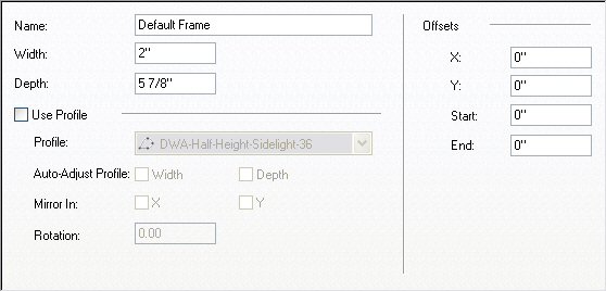
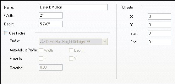
  • The “equal” in equal Cells refers to the distance between grid lines. Unless offsets are applied to the Frame or Mullion, the outer grid lines occur at the outside edge of the Frame, while the inner grid lines are centered on the Mullions. This means that the light opening of the start and end Cells will be reduced by the full width of the Frame, plus half the width of a Mullion, while interior Cells will only be reduced by the width of a Mullion. If both Frame and Mullion are the same width, the Start and End Cells’ light opening will be less than the light opening of the Middle Cells.
  • The grid lines of a nested Curtain Wall Unit are spaced evenly, based on the location of the parent Door/Window Assembly or Curtain Wall grid lines bounding that Cell, not on the light opening of that Cell. The Frame of the Curtain Wall Unit will be located at the light opening of the Cell, but the locations of “equal Cell” Mullions may not generate equal light openings in the Start, End, Top or Bottom Cells.
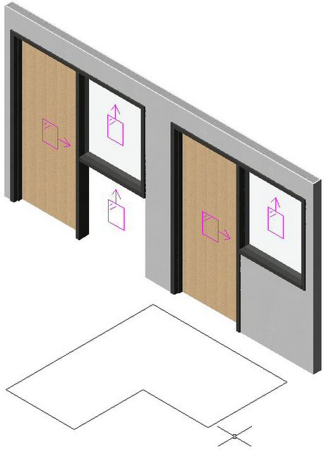
Figure 1
Equal Cell Door/Window Assembly with Equal Cell Curtain Wall Unit Infill
Blue Dimensions – Gridlines; Red Dimensions – Light Openings (Typical in all Figures)

If you keep the above in mind, it is possible to create equal light openings, and we will take a look at some techniques to do so, starting with the outer Door/Window Assembly or Curtain Wall, and then looking at the impact those choices have on a nested Curtain Wall Unit. A Door/Window Assembly will be used for these examples, but the techniques also apply to Curtain Walls.

There are several ways to generate equal light openings in the parent Door/Window Assembly or Curtain Wall.
  • Frame Offset: This might be acceptable for a Curtain Wall, since it does not create its own opening, although the Curtain Wall’s overall length and height will not represent the overall Frame dimension. For Door/Window Assemblies that are anchored in a Wall, offsetting the Frame pushes it into the Wall, leaving part of the Frame buried in the Wall, which is not acceptable.
  • Mullion Offsets: By creating multiple Mullions with varying offsets, assigned to the proper locations, equal light openings can be created. For example, three equal openings can be created when the Frame and Mullion widths are equal by setting up a vertical Division with three equal Cells and then creating two Mullions, each offset by 1/6 of their width toward the middle, resulting in each Cell losing 1-1/3 of the Frame/Mullion width. This can get rather complex when there are five or more equal openings to be created.
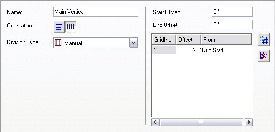
  • Start/End Division Offsets: This is the easiest method, and can also accommodate the case where the Frame and Mullion dimensions are not equal. Simply subtract one half the width of the Mullion from the Frame width and use that for both the Start Offset and the End Offset of the Division. This will make the Start and End Cells wider than the Middle Cells, resulting in equal light openings no matter how many Cells are specified, without the need to create offset Mullions.

Figure 2
Equal Cell Door/Window Assembly with 1.5 Start and End Offset

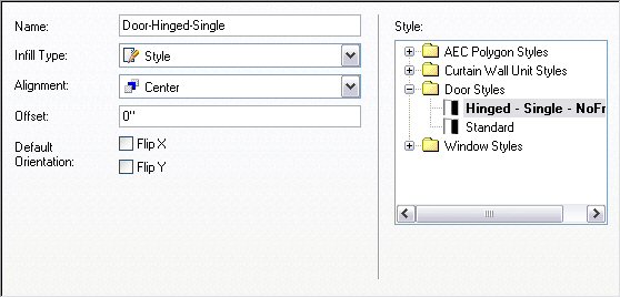
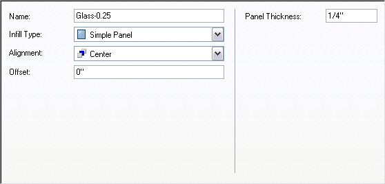
For a Simple Panel, Door or Window Infill, using the Start/End Division Offset method is the way to go, as these elements will be sized to fit the light opening of the Cell in which they are placed. If you can achieve your desired Muntin pattern by using the Muntins in a Window Style, that may be the best way to get equal light openings in a style that works for any overall Frame dimension, using a single Infill style.
Figure 3
Equal Cell Door/Window Assembly with 1.5 Start and End Offset
Window Style Infill with 0 Width Frame and 1 Width Sash and Muntins

If you need the greater control over spacing that using a Curtain Wall Unit for Infill can provide, there is a small problem with using the Start/End Offset method – the applied offset makes the outer Cells wider, but does not move the grid lines from the outside edge of the Frame, so the same Curtain Wall Unit Style can not be used for all Cells. (The Mullion Offsets method may also have the same problem, because the light opening is likely not centered on the gridlines in all of the Cells.) Fortunately, two copies of that Curtain Wall Unit Style, one with a Division Start Offset and one with a Division End Offset equal to the Offsets applied to the parent object can be quickly created, assigned to an Infill and used in the Start Cell and End Cell respectively. This gives you the look you want, while maintaining the flexibility of being able to change the overall Door/Window Assembly dimensions.
Figure 4
Equal Cell Door/Window Assembly with 1.5 Start and End Offset
Curtain Wall Unit Style Infill – Three Similar Styles:
1.5 Start Offset in Start Cell, No Offsets in Middle Cell, 1.5 End Offset in End Cell
(3.5 Offset Top and Bottom at Horizontal Division, All Three Styles)

Here is an example of a more complex muntin pattern. A series of nested grids, all using a fixed number of Cells, was used to create the pattern. Start and or End Offsets were applied as needed to get the equal light openings shown. This can be a little tricky to set up, since the nested grids for the Start and End Cells also need to have offsets applied, but once you have it set up, you can create a Door/Window Assembly with any overall length and height and maintain equal light openings.
Figure 5
Equal Cell Door/Window Assembly with 1.5 Start and End Offset
Curtain Wall Unit Style Infill with Offsets Applied to Multiple Divisions as Necessary

September 23, 2008

Equal Lights in the AU Newsletter

October 26, 2009 Update: The links to the article on the AU Online site no longer work and have been removed. The article has been republished in this blog article. The link below to the drawing file used for the images in the article remains valid.

The September 2008 edition of the AU Quarterly Newsletter is out. This issue adds links to technical articles, along with the usual AU news, including one on creating Door/Window Assemblies and Curtain Wall Units with equal light openings.


You can find the file with the Door/Window Assemblies that generated the images for the article in this thread in the AutoCAD® Architecture Content Discussion Group.

January 15, 2006

Door/Window Assembly Frame Depth in Window Schedule


In a thread in the Autodesk Architectural Desktop 2005 Discussion Group, I have posted a sample file that shows how both Windows and Door/Window Assemblies can be included in the same Schedule Table and have a Frame Depth column report values for both, even though Door/Window Assemblies do not have an automatic Frame Depth property. The example uses a style-based manual property to hold the Frame Depth value for the Door/Window Assemblies, and includes a formula property to pass through the appropriate value, depending upon the object type, so that one column can include the automatic property for Windows and the manual property for Door/Window Assemblies.

The thread includes a fairly extensive explanation of the properties I added to the out-of-the-box FrameStyles Property Set Defintion, so I will not repeat the explanation here. Be sure to download the DWADepthInSchedule2.zip attachment from my later post to get the revised Schedule Table that includes the manual DWAFrameDepthUnformatted property.

The sample file also makes use of a custom Classification Defintion called WindowSchedule, which is used to designate which Window and Door/Window Assembly styles are to be included or excluded in the test Window Schedule I added to show the results. By setting the Casement - Frameless Window Style to "NoSchedule", this style, used as an infill for the Door/Window Assemblies, is automatically filtered out of any selection set used for the Schedule Table.

August 01, 2005

Door/Window Assembly With Half-Height Sidelight

In a post to the AUGI ADT General Forum, I attached a sample file that demonstrates how you can create a Door/Window Assembly that has a Door with a "half-height" sidelight adjacent to it - that is, the top of the sidelight frame aligns with the top of the door frame, but the sidelight does not continue all of the way to the floor.

I started out by copying the out-of-the-box Hinged - Single door style, renaming the copy to Hinged - Single - NoFrame and setting the frame width to 0", to create a frameless door style for use as an infill in a Door/Window Assembly. Then I created a new Door/Window Assembly style called Door - Half-Height Sidelight and set up the following elements:


Main-Vertical Division


Sidelight-Horizontal Division


Door-Hinged-Single Infill


Glass-0.25 Infill


Default Frame Frame


Default Mullion Mullion

The out-of-the-box Doors & Windows.Glazing.Glass.Clear material was assigned to the Glass-0.25 Infill; the Default Frame and Default Mullion components had the Doors & Windows.Metal Doors & Frames.Aluminum Frame.Annodized.Dark Bronze.Satin material assigned [mostly because it came in with the Hinged - Single Door, which has the Doors & Windows.Wood Doors.Ash material assigned to the door panel].

I renamed the Primary Grid to Door-Sidlight, managing to omit the "e" in "Sidelight" in my haste. The assignments for this grid are shown below. Note that a nested grid is assigned to the End cell. This "New Nested Grid" was renamed Sidelight [and spelled correctly, this time]. Also note that Default Frame is only assigned to the left, right and top - the bottom frame is omitted, as we do not want one at the door and the sidelight does not extend to the floor.


The Sidelight Grid assignments were made as shown below.


A 6'-6" wide x 7'-2" high instance of this Door Window Assembly style was inserted in an out-of-the-box Stud-3.625 GWB-0.625 Each Side wall. I changed to a SE Isometric view and turned on the infill markers by selecting the Door/Window Assembly, right clicking and choosing Infill>Show Markers from the context menu. With the Door/Window Assembly still selected, I right clicked and chose Infill>Override Assignment... from the context menu, and then selected the infill marker in the lower half of the sidelight cell. I chose the Remove Infill and Frames option in the Infill Assignment Override dialog and selected OK. I then transferred the Design Rules to the object [select Door/Window Assembly, right click, choose Design Rules>Transfer to Object] and then transferred them back to the style [with Door/Window Assembly still selected, right click, choose Design Rules>Save to Style... and then check Transfer Infill Overrides to Style in the Save Changes dialog and click OK]. These overrides are now part of this style and will be applied to all instances of this style. This style is illustrated on the left side of the image below. Notice that even though the bottom cell of the sidelight and its frame are turned off, the wall does not fill in below the sidelight. If you are only interested in a plan view of this assembly, you are essentially done [depending upon the cut plane height and the height at which you set the bottom mullion of the sidelight, you may need to add a manual cut plane to see the mullion]. But if you want to generate an elevation or do a 3D view/rendering, you will need to do one more thing to get the results shown on the right Door Window Assembly.


SE Isometric View ;Posted by Picasa

In order to get the wall to fill in under the sidelight, you will need to create a profile that describes the outline of the outer edge of the frames/mullions and the floor line, then assign it to the style. Draw a LWPOLYLINE in the desired shape. In the Style Manager, create a new Profile [under Multi-Purpose Objects], give it the desired name, then right click the profile name and choose Set From... on the context menu. Select the polyline and choose an insertion point; I chose the lower left corner [door side]. Note that assigning a profile will effectively fix the dimension of the Door/Window Assembly. You can change the width, and the profile will be scaled to match, but you will get undesirable 3D results - as the width is made less than that used when drawing the profile, the door mullion below the sidelight will start to disappear, and eventually the door will also be notched. As the width grows larger than the original profile width, the wall infill will fall short of the door mullion below the sidelight. In the sample file, I created a copy of the original style, then assigned the 6'-6" wide profile to it. This would allow me to make additional copies of the original style and assign profiles with different widths, if needed.

April 29, 2005

Door/Window Assembly Sample Style

In response to a thread concerning Door/Window Assemblies in the Autodesk Architectural Desktop 2006 Discussion Group, I posted a sample style to the Autodesk Architectural Desktop Content Discussion Group. The 2006 Discussion Group thread also contains a link to a sample style by Paul Humphrey and a sample style attached by Jeff Hanson.

The original request in the thread was for a way to have a fixed, 3'-0" wide by 7'-0" high door in the middle of a storefront frame, flanked by equal panels at a maximum width of 4'-6". In my style, I chose to set both the default frame and default mullion to the same size, 2" wide by 4 1/2" deep. The Primary Grid is assigned a vertical manual division with gridlines set at plus and minus 1'-7" from the grid middle. This sets the width of the center cell for the door. The all of the cells in the primary grid are assigned a nested grid.

The nested grid for the start and end cells of the primary grid have a vertical fixed width division with the cell dimension set to 4'-6". Auto-adjust cells is turned on and set to "Grow" - all three "specific cell" options are unselected, to generate equal widths. The default infill is used for these, which I modified to be 1/4" thick and to which I assigned a glass material.

The nested grid for the remaining cell [all unassigned] is a horizontal manual division with a grid line set at 7'-1" from the grid bottom, fixing the door height at 7'-0". The bottom cell in this grid is assigned a frameless door style, so that the door itself will fill the opening; the top cell [all unassigned] gets the default infill. A frameless door style is nothing more than a door style where the frame width has been set to 0.

After placing an instance of this Door/Window Assembly, I edited the infill of the cell with the door and turned off the bottom frame for that infill, so the door gets the full 7'-0" opening height. I transferred the Design Rules to the instance, then back to the style, saving the override to the style so that the door cell will always have the bottom frame removed. You can read a more detailed explanation of how to do that, along with how to turn off the display of sills while turning on the display of the bottom frame, to get the lines out of your door opening in plan view [which I did NOT do in the initially posted sample file] by reading a previously posted article, "Removing Unsightly Bottom Frames at Doors". Here is something that I just discovered - unachored [no wall selected when placed] Door/Window Assemblies will not automatically display the frame below, even when that component is turned on, whereas those anchored to walls will. You have to use the same trick used for Curtain Walls, and set a manual cut plane that passes through the frame on the Other tab of the Plan Display Representation [or whatever Display Representation is active for a top view direction in the Display Configuration you use for plan views]. A height of 0 works if the bottom of your bottom frame that is at that elevation.

Note that if your Door/Window Assembly overall height is not at least 7'-2", the door will be less than 7'-0" tall, since the cell will be less than that. Heights over 7'-2" and up to 7'-4" are "weird" in that the mullion gets drawn and, until you hit 7'-4", is pushed into the top frame. At 7'-4", the mullion and frame are side by side; over 7'-4" and you get some transom glass.