July 28, 2008

Copy/Paste and Formulas

If you have ever set up a "test" Property Set Definition to work out a Formula property, then wanted to copy and paste the final formula to a Formula property in another Property Set Definition, you may have noticed that while the text will copy and paste just fine, the all-important references to other properties get converted to inactive text. For example, suppose I wanted to copy and paste the HeightSchedule formula shown in the image below.If I simply highlight the formula text, copy it to the clipboard with a CTRL-C, and then paste it into a new Formula property with a CTRL-V, I will get the following:

While I could highlight each former reference, then double click that property in the Insert Property Definitions area to replace the text version with an active property reference, that could become tedious, particularly if there were a large number of references to replace. The following technique can ease the pain, by avoiding the need to carefully highlight each individual reference. All you need to do is start the new Formula property, add a property reference for each instance in the original formula (I like to add a few returns first)...
...and then paste the formula in front of the property references you added. You will get something like this,
where the references in the pasted formula become active, while the previous references revert to inactive text, all nicely grouped together at the end, just waiting for you to highlight them all at once and delete them.

I have no idea why this works, but it does, and can be quite a time saver. I "discovered" this one time when I was pasting part of a formula that happened to have a property reference that was also repeated later on, after the part I was pasting. I was amazed that an active property reference pasted, annoyed when I noticed that the later one had become inactive and finally thrilled when I realized I could make use of that phenomenon to make pasting formulas easier.

July 25, 2008

Update 1 Available for AutoCAD® Architecture 2009

The first "update" (formerly known as "service pack") for AutoCAD® Architecture 2009 was made available today. You can get it through "Live Update" in the Communications Center or by going to the appropriate page of the Autodesk Website. There are separate updates for the 32-bit and 64-bit variants.

June 16, 2008

Text Case and the Quantity Column

A recent thread in the Autodesk AutoCAD® Architectural Discussion Group called my attention to the fact that, like the way real numbers are evaluated when including a quantity column in a Schedule Table, text strings are also evaluated using the "raw," or input value, and not the value that results from applying the Property Data Format assigned to the property (or to the property's column in the Schedule Table Style).

So, for example, even though the Schedule Table displays your text value in all capital letters, if the data is entered in different mixes of upper and lower case letters, only those objects whose data were entered identically will be collapsed into one line. In the example files I posted to the thread noted above, I created a manual, text-type property in an object-based property set, and applied the out-of-the-box Case - Upper Property Data Format. I entered the characters, but all upper case for some and all lower case for others. I kept the Case - Upper formatting on the column in my Schedule Table Style, and even though the data appears identical in the Schedule Table, the values entered in upper case collapsed into one line and those entered in lower case collapsed into another.

Fortunately, the workarounds similar to those suggested for real numbers will also work for text values that you can not guarantee will be uniform. If you can not use a List to assure that all values are entered identically, and you have a Property Data Format that formats the text the way you want, simply set up a formula property and pass through the formatted manual property enclosed in double quotation marks. For a manual property called WindowType, the formula would look like this:
"[WindowType]"
where [WindowType] is a property reference selected from the pane below the formula editing pane.

If you need to force all upper case or all lower case text, and do not want to create or rely on a Property Data Format, then you could use the UCase or LCase VBScript functions to achieve that result, respectively:
UCase ("[WindowType]")
While you might be able to replicate sentence case or title case with a more complicated VBScript statement, I would recommend creating a Property Data Format that applies the desired format to the manual property and then pass through the value in quotation marks for either of these formats.

Keep in mind that in later releases, you can choose to not display the formula property in the Properties palette or in the Edit Property Data dialog. The user can not edit the value anyway, and omitting it here will reduce clutter as well as eliminate inquiries as to why there are two properties with what appears to be the same value. Just remember to use the formula property in your Schedule Table Style, not the manual one.

June 07, 2008

InputHistoryMode System Variable


I do a lot of keyboarding when using ADT/ACD-A, and I have grown quite used to using the up and down arrows to scroll through previously keyed in data. Unfortunately, I always forget which system variable controls this, and what setting I need to get what I want.

After a long search in the Help and on the Discussion Groups, I finally found the system variable in the Help - INPUTHISTORYMODE - and armed with that, found an old post of mine that contained the setting I prefer. I find the descriptions in the Help of the various bit settings somewhat misleading, as what I want to enable is the ability to get previous input with the up and down arrows (which the Help implies is enabled by the one bit) and get rid of the useless-to-me display of previous coordinates (which the Help implies is enabled by the eight bit). The default setting, 15, has all bits enabled, and you get the tiresome coordinates, instead of previously typed input. Clearing the eight bit, which is what I would have expected would do the trick, does not; clearing the one bit does, so my preferred value for this variable is 14.

I am making this post to my blog to make finding this information easier for me in the future; if it is helpful to others, so much the better.

May 16, 2008

Space Generation in ACD-A 2009 with AutoCAD® Object Boundaries

Several recent posts in the AutoCAD® Architecture Discussion Group have asked why AutoCAD objects can no longer be used as boundaries when automatically generating Spaces, as they could in previous releases. The good news is that you can still use AutoCAD objects, and now you have more control over which objects are seen as Space boundaries. The "bad" news is that you have to tell ACD-A 2009 which AutoCAD objects are space bounding; this is done by setting the newly added Bound space property of the AutoCAD object, found in the Advanced category on the Design tab of the Properties palette, to "Yes".
If the drawing file in which you are working has no AutoCAD objects set to bound Spaces and has no AEC objects that are capable of forming a Space boundary, you will be presented with this helpful dialog, which allows you to either make all visible objects capable of bounding Spaces, or to select the objects you want to have capable of bounding Spaces.
So you can still quickly add Spaces to any "old" file (or any new file you get from someone using vanilla AutoCAD) - just remember to set the Bound spaces property of the linework you want to use as boundaries to Yes.

May 11, 2008

Review: CADaptation’s AecBatchStylesEditorTM 2008

On April 15, 2008, CADaptation released AecBatchStylesEditorTM 2008, an application that runs inside of either AutoCAD® Architecture 2008 or AutoCAD® MEP 2008. The AecBatchStylesEditor greatly enhances the user’s ability to work with styles and definitions in these host applications, particularly when the same, or very similar, settings are required for multiple styles or definitions.

FULL DISCLOSURE: I “know” the two main people at CADaptation, Corey Layton and Brian Winterscheidt, from our mutual involvement with the Autodesk AutoCAD Architecture Discussion Groups. I served as a beta tester for AecBatchStylesEditor 2008 and received a complementary copy of the application for doing so.

AecBatchStylesEditor 2008 allows the user to perform batch edits on the Property Sets, Materials, Classifications and Display Properties associated with multiple styles or definitions. Very often, these settings are the same, or very similar, across multiple (if not all) styles/definitions of a particular object type. With AecBatchStylesEditor 2008, you will still need to create/attach the first instance of one of the previously listed items in the host program the way you do now, but you can then copy that from the style/definition where you created it to as many other styles/definitions of that object type as you like. This frees you from the drudgery of manually making the same edits over and over to multiple styles (and then checking what you did to make certain you really did the exact same thing multiple times). If you do need some minor variation between styles, AecBatchStylesEditor 2008 can get you 90% done very quickly, leaving only the variations to be manually edited. Many operations also allow you pick and choose settings from what you are copying, so you can copy just the subitems that are the same.

The following example should give you and idea of what this application can do. The CADaptation website offers a free trial version that only works on Mass Elements if you want to see the program in action for yourself.

Suppose you were working with the “new” out-of-the-box Space Styles, with their fancy colored fills in Medium Detail, but needed to have those same fills display when the Low Detail Display Configuration is set current. Unfortunately, while the color and layer set for the Low Detail Display Configuration is the same as that for the Medium Detail, the out-of-the-box settings when the Low Detail Display Configuration is chosen display a series of lines at 45 degrees, rather than the solid fill. And then, when you go to check just how those color fills were assigned, you discover that it is all done as style-level overrides! That means changing the hatch type for the Plan Low Detail Display Representation for every Space Style used in the drawing. AecBatchStylesEditor 2008 can make quick work of this tedious task. This is one of my favorite features in the application, and not just because it is the result of a suggestion I made during the beta process.

AecBatchStylesEditor 2008 provides a number of ways to start the application:
  • Tool Bar Button.

  • Tool Palette Tool.

  • Pulldown Menu

  • Typing AecBatchEdit at the Command: prompt.


In the AecBatchStylesEditor dialog, I have selected the Display Properties tab, as the change I want to make is to the Display Properties of Space Styles. The first step will be to select Space Styles in the Object Type to Edit in the upper left corner. You can also choose an object type and set a source style by using the Pick… button on the left side. If the task at hand is copying the settings from a specific style to one or more other styles, this would be the way to go. Since the sample task involves copying settings from one Display Representation to another Display Representation within each selected style, I will use the tree window to select Space Styles, under the Architectural Objects node (just like Style Manager!). This populates the rest of the tab with data and options, based on the object type selected and the styles of that object type available in the current drawing. In order to quickly select all styles as styles to edit, I entered an “*” in the Enter Selection Filter edit box (without the quotation marks). This conveniently happens to be the initial default when left clicking in the box. Select the Go button to register the filter, and all of the Space Styles within the drawing will be checked in the Styles to Edit list box at the lower left. If you wanted to, you could uncheck any that you did not wish to edit.

In the Source Display Options area in the upper right of the Display Properties tab, I checked the Copy between Display Reps within each Style to Edit. This grays out the Source Style option on the left side, because instead of one style serving as the source, the values of the source Display Representation of each individual style will be copied to the Display Representation(s) to be edited in that same style. I then chose the Plan Display Representation as the Source Display Rep, using the drop down list isn the Source Display Options Area. Doing this automatically checks the Plan Display Representation in the Display Rep(s) to Edit list. The final step is to check the Plan Low Detail Display Representation in that same list, as this is the one to which I want to copy the settings from the Plan Display Representation.

Since I want to copy all settings between the corresponding Display Representations and I want to maintain them as style-level overrides, I am done with making settings. If I wanted to be more selective, I could use the other areas on the right side of the dialog to narrow down the settings to be copied or to set up a custom mapping of settings. Selecting OK tells the application to make the selected changes, and after processing all of the Space Styles in my test drawing file, the AecBatchStylesEditor Log dialog appears, as I have the logging option enabled, on the Preferences tab. This dialog displays a listing of the changes that were made, and I can save it to a text file if I wish, for later examination. Closing the log dialog returns me to my drawing file, with an offer to save the drawing, since I also have that option enabled on the Preferences tab. More importantly, my Low Detail Display now shows solid hatches, just like the Medium Detail Display, and all 38 of the Space Styles that were in this drawing have had the Low Detail Display Representation Style-level Display Override edited to match the Medium Detail Display Representation in just a few minutes.

If the out-of-the-box Display Settings are not exactly to your firm’s liking, but you have been putting off making changes because of all of the repetitive editing that might need to be done, or if you have wanted to create new Display Configurations with new Display Representation Sets and new Display Representations, but were overwhelmed by the enormous task of making all of the settings (particularly if they are the same as the settings for an existing Display Representation for all but a few object types), then you will definitely want to take a look at what this application can do. If you make use of style-level display overrides (whether out-of-the-box or custom), you can also use this application to push any drawing-default level changes you make to components that were not the reason for the override, without having to edit each override manually. Unless you are extremely underpaid, one or two uses on what would have been complicated or repetitious tasks will save you enough time to recoup the cost of the application, and every use after that is gravy.

Another Step Closer to Eliminating Printed Documentation

The last several releases of AutoCAD® Architecture/Autodesk® Architectural Desktop have not been accompanied by printed manuals, but you could, if you so desired, order one manual per license, which would be shipped to you at no charge.

In previous years, the options were to choose between the AutoCAD manual, the Imperial Tutorial for AutoCAD Architecture/Autodesk Architectural Desktop or the Metric Tutorial. I was disappointed that a printed manual for AutoCAD Architecture/Autodesk Architectural Desktop was not a choice, but was glad to have access to a printed version of the AutoCAD manual.

For the 2009 release, there are still three choices, but the AutoCAD manual is not one of them. Instead, in addition to the usual Imperial/Metric tutorial options, the other choice is to get a copy of the ACA Getting Started manual. At first, I was thrilled to see that an ACA manual was available, but something about the name seemed familiar. A quick check of the box in which the disks for AutoCAD Architecture 2009 were shipped revealed the source of that familiarity: the booklet included with the disks is called "Getting Started" and the part number on the back, 185A1-050000-PM01A matches that on the website ordering page. (Click on any image to see a larger version; use the Back button to return here.) So unless you want additional copies of the sixty-nine page Getting Started booklet that comes with the disks, you may want to consider one of the other choices.

Given the major change to the user interface, the AutoCAD manual would have been useful. While I love being able to search the electronic Help, I am sufficiently old-school (and sufficiently old) to still value a printed manual, that I can use without having to sacrifice screen space with the application running (does everyone but me have dual screens now?) and can also peruse when I am away from the computer.

I wonder if vanilla AutoCAD users still have the option to get the full manual, or just a "getting started" booklet.

May 01, 2008

Property Set Tools

While this feature was added way back in the 2006 release, I suspect that many are not aware of its existence. As you may recall, that release added Schedule Tag tools, providing an easier way to create and use Schedule Tags. Mastery of the AEC Content Wizard was no longer required!

One of the abilities of Schedule Tag tools is that you can specify additional Property Sets to be attached when tagging, even if those sets are not referenced by the Schedule Tag itself. Not only that, but you can also have the tool only add Property Sets, and dispense with the Schedule Tag altogether. An external source file can be specified to serve as the source of the Property Set(s), if the set(s) is(are) not already defined in the target file.

If you have ever wanted a tool that would attach Property Sets without adding a tag, simply make a copy of an existing Schedule Tag tool and edit the tool's properties. For example, in the 2008 release, I copied the out-of-the-box non-project-based Door Tag tool and pasted it on an editable tool palette.Right clicking on the tool and choosing Properties... from the context menu...
...opens the Tool Properties dialog, as shown below. This tool is a "Tag" type tool that currently does not add any Property Sets other than those referenced in the Schedule Tag, since the Property data property is empty.
If you left click on the Type property, you will get a pulldown menu with two choices: Tag and Property set data, as seen below. Change this from Tag to Property set data...
to have the tool attach Property Sets without adding a tag.
The tool you copied may point to a source file other than the one where your properties are kept. If so, simply left click on the Property def location property, and choose Browse... from the pulldown list.
This will open a standard file selection dialog that will allow you to navigate to the folder holding your source file and select that source file. With the proper source file chosen, left click on the Property data property, and choose the property or properties you wish to have the tool add from the Add Property Sets worksheet that displays. You can choose from both object-based and style-based Property Sets, keeping in mind that if you add a style-based set to an object, all objects of the same style will also have that Property Set added.
Select OK to register your choice(s), and then OK again to save the changes you made to your tool. Its as simple as 1, 3, 2 - and your tool is good to go. For a truly professional look, you may want to create a custom image file for your Property Set tool and add that to the tool (right click on the image in the Tool Properties dialog and choose Specify Image... from the context menu to specify the image file you created). Unlike tools that reference visible drawing objects, there is no "automatic" image for a Property Set only tool; the tool will retain the original image from the tag you copied unless you manually replace it with another image.

One feature I would like to see added is the ability to drag and drop a Property Set from Style Manager onto an editable tool palette to create a Property Set tool. Unfortunately, that is not possible in the 2008 release. Sounds like a good addition to the Wish List.

April 30, 2008

Help Pick AU 2008 Courses!


In his BLAUG blog, Autodesk's Joseph Wurcher has posted a link to a survey where you can help select the courses offered at AU this year. They have uploaded all of the course proposals and divided them up into categories. You can vote for up to 15 courses that you would like to see at this year's AU. You can vote in more than one category, but the overall limit of 15 courses applies.

But hurry - voting closes on Saturday, May 3, 2008!

April 27, 2008

ACD-A Display System - Part 3, Viewing and Editing Display Settings

First Article in the Series: ACD-A Display System - Part 1, AutoCAD® Basics
Previous Article in the Series: ACD-A Display System - Part 2, Big Picture Overview

Before getting into the details of the Display System, a discussion of the ways in which display settings can be viewed and edited is in order. There are five ways to gain access to the Display System and its settings. Which one to use will depend on the task at hand and, where more that one will do, with your preferred means of working.
  • Display Tab of the Drawing Setup Dialog.
  • Display Manager.
  • Display Properties Tab of a Style or Definition Properties Dialog.
  • Display Properties Tab of the Object Display Dialog.
  • Display Tab of the Properties Palette.
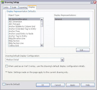
Display Tab - Drawing Setup DialogYou may not have noticed this tab before, especially if you do not open this dialog very often now that you can set the drawing scale on the Drawing Window Status Bar. (You can access this dialog through the Open Drawing Menu - found on the left side of the Drawing Window Status Bar, the left pointing arrow in a circle icon, or from the Format pulldown menu.) Those who have been using AutoCAD® Architecture long enough may recall that prior to Release 3, this was the only way to view and edit the Drawing Default display settings of any object, without having an instance or a style/definition of an object type in the drawing. The interface here is not as slick as the Display Manager, but if you find this more to your tastes, then by all means use it. Most, however, will consider this an interesting relic and will prefer to use the Display Manager for Drawing Default editing.
Display Manager
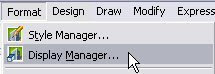
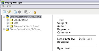
The Display Manager gives you access to the Drawing Default settings for Display Representations, as well as to the settings for Display Representation Sets and Display Configurations. Anyone who is serious about making significant changes to the Display System needs to be very familiar with the Display Manager, which can be opened by choosing the Display Manager... item on the Format pulldown menu.It is also available via a button on the CAD Manager toolbar button if you have the CAD Manager CUI loaded as a partial CUI.The Display Manager Dialog has File and Edit pulldown menus, a tool bar, two main panes, left and right, and the usual OK, Cancel, Apply and Help buttons. Most of the action will take place in the left and right panes. The left pane is a tree view pane, that allows you to navigate the various parts of the Display System. Since the 2006 release, all open drawings are shown in the left pane, and you can use the Open toolbar icon or File > Open drawing... from the pulldown menus to open a file in Display Manager that is not open in AutoCAD Architecture. Earlier versions will only give you access to the display settings of the file that was currently active when the Display Manager was opened.

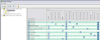
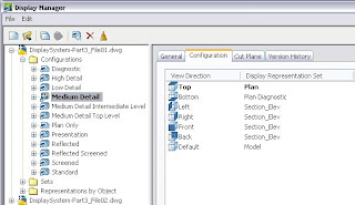
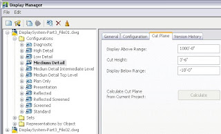
Configurations: Use the left pane to find the part of the Display System you want to examine or edit, then view the settings and make any desired edits in the right pane. The information shown in the right pane will vary, depending upon what is selected in the left pane. For example, selecting the Configurations node for a particular drawing shows a matrix in the right side with the Display Configurations (Configurations) in that drawing listed in the rows and the Display Representation Sets (Sets) in that drawing listed in the columns. An icon appears in the matrix to indicate that a particular Set is active in a particular Configuration. The icon displayed varies with the view direction to which the Set is assigned. A "see-through" cube indicates that the Set is assigned to the Default view direction, while a cube with a "solid" top face indicates the Set is assigned to the Top view direction. A key of all of the icons used for Configurations in the Display Manager can be found in the 2008 Help, by navigating through the following on the Contents tab: AutoCAD Architecture 2008 Help > AutoCAD Architecture User's Guide > Workflow and User Interface > Display System > The Display Manager > Viewing Display Configurations (other versions likely have a similar page).Expanding the Configurations node in the left pane will reveal a list of the Display Configurations in that drawing (the same ones that were listed in the rows of the matrix above). Note that one of these will be in BOLD type, indicating that it is the currently active Display Configuration. This graphic convention carries through for Display Representation Sets, making it easy to know whether the edits you are making will affect the current display. Selecting one of these will display several tabs in the right pane. The General tab displays the Configutation name, description and allows for adding notes, if desired. The Configuration tab shows a list of the standard view directions and the Display Represenation Set assigned to that view direction for that Display Configuration, if any. The Display Representation Set assigned to the Default view direction is used for all view directions that are not one of the six standard orthogonal view directions, as well as for any of those six that is not assigned a Display Representation Set.The Cut Plane tab allows you to set the cut plane height for the Display Configuration, as well as the above and below ranges.The Version History tab is used in conjunction with Project Standards (a subfeature of the Drawing Management/Project Navigator feature). Expanding a specific Display Configutation node in the left pane will show a list of the Display Representation Sets assigned to that Configuration. Selecting one of these displays the same set of tabs that display when selecting a Display Representation Set under the Sets node (shown below). Just keep in mind any changes made here will affect all uses of that Display Representation Set, not just its use in this particular Display Configuration.

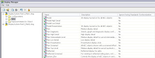
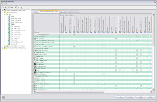
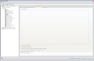
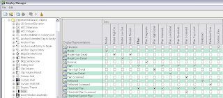
Sets: Selecting the Sets node in the left pane displays a list of the Display Representation Sets defined in that drawing, with the description of each and the ability to set whether or not a give Display Representation Set should be ignored during Standards Synchronization.Expanding the Sets node in the left pane displays a list of the Display Representation Sets (BOLD type indicated the currently active one). An explanation of the icons displayed next to the Display Representation Sets can be found in the 2008 Help: AutoCAD Architecture 2008 Help > AutoCAD Architecture User's Guide > Workflow and User Interface > Display System > The Display Manager > Viewing Display Sets. Selecting one of the Sets displays several tabs in the right pane. The General tab offers the same options as the General tab for Configurations. The Display Represenation Control tab, which offers a matrix of Objects on the rows and Display Representations on the columns. On each object row, a toggle appears in the column for every Display Representation that is defined for that object type. If a check mark appears in that toggle, then that Display Representation for that object type is active in the selected Display Representation Set. A left mouse click on a toggle will change the status - checked (active) or unchecked (inactive). A right mouse click on a toggle offers a context menu with three options: Select All (make all Display Representations for that object type active), Clear All (make all Display Representations for that object type inactive) and Edit... (edit the display settings for that particular Display Representation/Object Type. Display Representations can also be edited as noted below under the Representations by Object node; keep in mind any edits made here will affect all uses of that Display Representation.The Display Options tab offers the ability to fine-tune your display settings based on Classifications (if any are defined in the current drawing) and control live sections and materials.The Version History tab serves the same purpose as it does for Configurations.

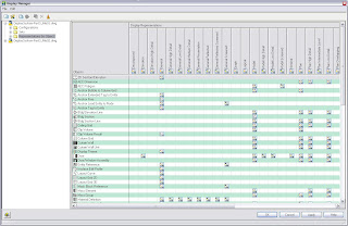
Representations by Object: Selecting the Representations by Object node in the left pane displays a matrix of Objects on the rows and Display Representations in the columns. In this matrix, an icon is displayed where the Display Representation of a given column is defined for the object type of a given row. An explanation of these icons (also used in the list of Display Representations below each object type - see below) can be found in the 2008 Help here: AutoCAD Architecture 2008 Help > AutoCAD Architecture User's Guide > Workflow and User Interface > Display System > The Display Manager > Viewing Display Representations. Right clicking on an icon displays a context menu with various options, including Delete (only works if the Display Representation for that object type is not referenced by a Display Representation Set), several options related to Project Standards (these may be grayed out if the selected drawing is not part of the current project, or a project is not set current) and Edit..., which allows you to edit that Display Representation for the given object type.Expanding the Representations by Object node in the left pane shows a list of the AEC object types in the drawing that interact with the Display System. Selecting one of these shows a matrix in the right pane, with a list of the Display Representations defined for that object type on the rows and the Display Representation Sets defined in that drawing on the Columns. A toggle occurs at each row/column intersection; a check mark indicates that the Display Representation of a given row is active for the Display Representation Set of a given column. A left mouse click changes the toggle status. A right click on a toggle displays a context menu that offers several choices: Duplicate (make a copy of the Display Representation), Delete (the Display Representation, will only work if it is not referenced by a Display Representation Set), Rename (only available for Display Representations that are not hard coded into the program), several Project Standards options (see note above under Sets), Select All (set Display Representation active for all Sets), Clear All (set Display Representation inactive for all Sets) and Edit Drawing Default... (edit the display settings for the Display Representation).Expanding the object node in the left pane displays a list of Display Representations defined for that object in that drawing. Selecting one of the Display Representations in the left pane displays tabs in the right pane related to the display settings for the selected object type. Some object types, such as Anchor Free, do not have any user-editable display settings, and the right pane will remain blank when selecting a Display Representation under these (note the grayed-out Display Representation icon in the left pane in these cases). We will get into more detail on the various tabs and settings in a future article.
Display Properties Tab - Style/Definition Properties Dialog
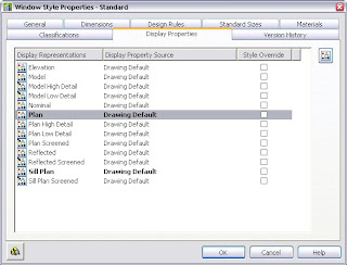
When editing a style or definition, the Display Properties tab will give you access to the display settings for that object type. On this tab, you can edit the Drawing Default level settings, if the override column toggle for that Display Representation is not checked. If the toggle is checked, or you add a check to that toggle, you can edit/create a style-level override for that style/definition/Display Representation.You can edit the display settings by selecting a Display Representation and then selecting the edit button in the upper right of the dialog. Setting an override will also open the Display Properties dialog for that Display Representation.

Display Properties Tab - Object Display Dialog
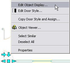
Selecting an object in your drawing and right clicking displays a context menu which includes Edit Object Display... as an option.Choosing this opens the Object Display Dialog; the Display Properties tab offers the same access to the Drawing Default display settings as seen when editing a style/definition, only here any override is applied at the object level, so it only affects the selected object.
Display Tab - Properties Palette
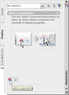
This is the new kid on the block, and it gives you the option to see changes "live". It also allows you to select the component you want to change in the drawing, without having to wade through a lot of dialogs to get to the setting you want. That can be something of a double-edged sword, however, in that the ease of making changes can result in ill-considered changes that could make a mess of the display settings in relatively short order, particularly when used by someone who does not fully understand the Display System. For that reason, I am going to defer any detailed discussion of this method until after I have covered the Display System in detail, using the methods of access noted above.You can also initiate the select component feature by selecting any object, right clicking and choosing Select Component from the context menu. You are not restricted to selecting components of the originally selected object.