Showing posts with label Schedule. Show all posts

February 26, 2016

Dynamo: Exporting All Schedules in a Revit Model

Autodesk® Revit® allows you to export the contents of a single Schedule View to a tab-delimited text file which can then be opened in a spreadsheet program, such as Microsoft® Excel® [Application Menu > Export > Reports > Schedule]. Handy enough, but what if you have multiple Schedule Views that need to be exported multiple times during the life of a project, as part of a defined information exchange? Individually exporting each Schedule View could quickly become tedious.

Let Dynamo deal with the tedium. A fairly simple graph will export all of the Schedule Views in a project.
This graph is set up to be run manually, as the user will need to use the Directory Path node to specify the folder into which the exported Schedule Views will be placed. The Element Types and All Elements of Type nodes gather all of the Schedule Views [ViewSchedule objects] in the project. The Element.Name and Code Block nodes create the file name for each exported Schedule View by concatenating the ViewSchedule Name with a ".txt" file extension. The Python Script node does the heavy lifting, taking a list of ViewSchedule objects, the directory path and a corresponding list of file names, generates the exported files, and returns a list indicating whether or not each item was exported.

Credit for the Python Script belongs to Dimitar Venkov, who posted a script for exporting a single ViewSchedule in this thread in the Dynamo forum. I modified that script to work with a list of ViewSchedules and a corresponding list of exported file names. A for loop processes each ViewSchedule in turn, and a list of the results is gathered and set as the node output.

Variations on this can be done to export a selected number of ViewSchedules. A simple version is shown below, in which the user has to set up a series of Views nodes, one for each desired ViewSchedule, and then generate a list by passing each one to an input of a List.Create node. A little labor intensive, but if you need to do this multiple times for a given project, you could save a copy with the needed ViewSchedules set up and then run it when new exports are needed

Antony McPhee posted examples using a string filter to export all of the ViewSchedules with a Name starting with a specified string to that same Dynamo forum thread.

January 19, 2016

Revit: Schedule Column Totals and Rounding

Schedules in Autodesk® Revit® that include a total for a column of numeric data is subject to the same issues with rounding that Schedule Tables in AutoCAD® Architecture have, as noted in this previous blog article, and expanded upon in this one. Both programs display formatted data in the schedule, which may involve rounding, but use the unformatted data when calculating the total for the column, and then formatting that total. If the data is rounded, then it is possible that the total displayed will not be the sum of the displayed values in the column.

In Revit, you can use one or more calculated value columns in the schedule to have the rounded value be the value that is used to calculate the column total, so the total will match the sum of the displayed values. The round() formula function will round to the nearest whole number. If you are displaying data to the nearest whole number, a single calculated value column, employing the round function will suffice. In the example shown in the screenshots below, the data is to be displayed with two decimal places. That requires a few intermediate calculated value columns. (Click on the image below to see it full-size.)

The Area Parameter column shows the out-of-the-box Area parameter for Rooms, rounded to two decimal places. The total of this column is 0.01 higher than the result you would get if you added the displayed numbers.

The Area Unformatted column is a calculated value column, that displays the Area parameter with eight decimal places. I included this just so you can see how the raw numbers total and then are rounded to get the total of the Area Parameter column. This column is not needed to generate the column with "correct" total.

In order to round the value to two decimal places, the first step is to multiply the Area parameter values by 100. The Area100 calculated column does that. The image below shows the formula.

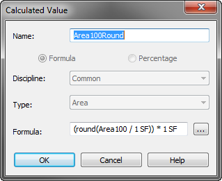
The Area100Round calculated value column rounds the Area100 value to the nearest whole number. The round function requires an unformatted real number, so it will not work on an Area value. To get around the "inconsistent units" problem, you have to divide the Area value by one square unit, do the rounding, and then multiply by one square unit, as shown in the image below.

The Area Fixed 2 Decimal is the calculated value column that you will want to have displayed in your schedule (but probably not with that column header). This column takes the value in the Area100Round column, divides it by 100 and displays the result with two decimal places. Since the values in the Area100Round column are all rounded to whole numbers, dividing by 100 leaves, at most, two decimal places, so Revit is adding the displayed numbers when calculating the total.

You do not have to apply eight-decimal place formatting to the Area100 and Area100Round columns; I only did that to more closely show the values that Revit is using internally. In the final schedule, you will want to hide the Area Parameter (the built-in Revit Area parameter), Area100 and Area100Round columns. You have to keep them, so the values are available to make the calculations. If you prefer, you can eliminate the Area100 and Area100Round columns by combining all of the math in one formula: ((round((Area * 100) / 1 SF)) * 1 SF) / 100. It is easier to explain what is being done using separate columns, which is why I took that approach here.

December 04, 2015

ACA: Underline in Tag But Not in Schedule III

This old post and this follow up post describe two ways to have a text property shown in a tag (such as a room name) be underlined in the tag, but not in a schedule table. The first post suggested adding a formula property, and concatenating %%u and the non-underlined property in the formula, and then using the formula property in the tag.

The second post accomplished the same thing by making a copy of the Property Data Format assigned to the text property and, in the copy, adding %%u in the Prefix field, and then assigning the new Property Data Format to the property in the Property Set Definition. When adding that property to a Schedule Table Style, the original, non-underlined Property Data Format would be used. The benefit of this method is that you do not need to make any changes to the view block used by the Schedule Tag's Multi-View Block Definition.

This all worked fine back in 2005/2006 when the articles were written, and for some time thereafter. I have not checked, but I suspect that the addition of multi-line attribute support for Multi-View Blocks (and, therefore, in Schedule Tags) in the 2009 release broke the recognition of %%u as a code to indicate starting (and stopping) an underlining of text. It certainly does not work in the 2016 release.

Fortunately, there is still a way to do this, and it can be used with either method. Just substitute \\L [the MText underline code] for %%u. For example, given a text property called Name, you could create a formula property that creates an underlined version of that property by using the formula
RESULT = "\\L" & "[Name]"
where "[Name]" is a properly created reference to the Name property.

Or, you could make a copy of the Property Data Format, such as Case - Upper, rename the copy Case - Upper - Underline, and add \\L to the Prefix property on the Formatting tab.

June 26, 2012

ACA: Occupancy Load Calculations with a Column Total

In the thread in the Autodesk AutoCAD® Architecture Discussion Group that was the basis for my previous blog article post on occupant load calculations, Ted Evans pointed out that if you add a total to the occupant load column, the sum may not reflect the total of the displayed values. He is correct, if the displayed values have a sufficient number of cases where small fractional amounts were rounded up. Because any fractional amount is being rounded up in this case, there is no opportunity for round ups to be offset by round downs, making the fact that ACA uses the unformatted values when calculating the total even more apparent than in a situation where rounding is done to "nearest".

My reply today explained the reason why the total was not the same as the sum of the displayed numbers, and I indicated that in order for the total to be correct, the rounding should be done within the formula property, rather than by the Property Data Format. [For other options, see this blog article, which includes several means of achieving real number rounding and getting correct column totals.]

By placing the results of each branch of the second If statement in a variable [occs] instead of making it the RETURN value, I was able to then process the value in variable occs. If occs is not a whole number (that is, if subtracting the integer portion of occs from itself does not result in a value of zero), the value of occs is reset to the integer portion of occs plus one. Otherwise, occs is a whole number, and rounding up is not necessary. The revised formula is shown below; a sample file was included in my reply in the Discussion Group.
occLoad = [SpaceStylesCalcs:Occupant_Load]

If occLoad = 0 Then
 doCalc = 0
 occLoad = 1
Else
 doCalc = 1
End If

If doCalc = 1 Then
 occs = [SpaceStyles:BaseArea] / occLoad
Else
 occs = 0
End If

If occs - Int (occs) <> 0 Then
 occs = Int (occs) + 1
End If

RESULT = occs

June 24, 2012

ACA: Occupancy Load Calculations and Division by Zero

A question concerning occupancy load calculations and how to handle Spaces to which an occupant load of "0" has been assigned was posted to a thread in the Autodesk AutoCAD® Architecture Discussion Group. Dividing the Space's area by the occupant load causes an error in the formula when the occupant load is zero. As noted in my response, which includes a sample file done in ACA 2011, a simple If statement cannot be used test for a zero value and then avoid the calculation, because VBScript will evaluate the entire statement, including logical paths that would not be taken, and still end up in an error condition.

My solution was to use a variable (called occLoad in the example) to hold the occupant load property value and two If statements. The first tests for a zero value and sets a variable (called doCalc in the example) to indicate whether or not a calculation should be done. If it finds a zero value, the doCalc variable is set to 0 (do not calculate) AND the occLoad value is changed from 0 to 1. If occLoad is not zero, the first If statement only sets doCalc to 1 (do calculate).

The second If statement then tests the value of doCalc: if it is 1, it returns the result of dividing the area by the occupant load; if it is 0, it returns 0. Because the first If statement assures that the occLoad value will not be zero, the division in the second If statement never results in an error condition, and the desired result for an occupant load of zero is returned.
occLoad = [SpaceStylesCalcs:Occupant_Load]

If occLoad = 0 Then
 doCalc = 0
 occLoad = 1
Else
 doCalc = 1
End If

If doCalc = 1 Then
 RESULT = [SpaceStyles:BaseArea] / occLoad
Else
 RESULT = 0
End If

The example file also shows how a Property Data Format can be used to round any result with a fractional amount up to the next highest integer, since you would want that when calculating occupant loads for egress analysis. It also demonstrates using a style-based Property Set to hold the occupant load property, so that the occupant load value only needs to be added to the Space Style, and not to each individual Space.

March 27, 2012

ACA 2013 - Grouping and Subtotals in Schedule Tables

The ability to group items within a Schedule Table and have subtotals for each group has long been wished for by AutoCAD® Architecture users, extending back to when the program was called Architectural Desktop. That wish has been granted in the 2013 release, which supports up to three levels of grouping and subtotals.

In the past, you have been able to sort by the values of one or more properties, which would get objects with the same value for a given property in close proximity. If you specified a quantity column in your Schedule Table (whether displayed or hidden), you could also get objects with identical values in all columns to collapse onto one line. For properties with numerical values, you could specify that the total of all items in the Schedule Table be shown at the bottom of the Schedule Table.
Tracking the area of Spaces is a common need in architectural design. The image above shows a sample schedule for Spaces, such as might have been created in a previous release. The Schedule Table is sorted first by the Space type (using the Style automatic property source to acquire the name of the Space Style) and has a quantity column to collapse identical lines. While the Schedule Table avoids the use of room numbers to have some identical rows, inevitably you will want to include data that will prevent all Spaces of a given type from collapsing on one line (if nothing else, the areas of the Spaces of one type are unlikely to all be identical in a real-world design), leaving you with multiple Total Areas for each type. The image below shows the "new" Sorting/Grouping tab (formerly just "Sorting") of the Schedule Table Style used to produce the Schedule Table shown above. The Group feature is not enabled for either of the columns being sorted.

While getting totals for each Space type in the sample Schedule Table above might not be too difficult, on a real project with tens or hundreds of Spaces, it could be quite a chore, and in the past, would likely have resulted in exporting the Schedule Table contents to a spreadsheet program, followed by additional formatting and manipulation to get useable subtotals. Doing this repeatedly as changes are made to a project in the early design phases can be tedious. In a copy of the previous Schedule Table Style, the Group feature for the SpaceStyles:Style property has been activated by checking the Group toggle under that property.
The Display Subtotals For Group toggle has also been checked. While you can override the formatting of the Group property, this was not done, as indicated by the "None" text; the Subtotal Format Override was used, however, to increase the height of the text from 3/32", as set on the Default Format tab, to 1/8", as indicated by the Height designation. The default Group Orientation of Column was kept. Group Row Repeat and Group Row Indent are disabled when using the Column orientation,. Group Row Separation was changed from None to Blank Row. The results can be seen in the image below.
When grouping by a property using the Column orientation, all items with the same value for that property are listed together ("grouped"). Instead of having that property value shown on each line, the individual row lines are deleted (including at the subtotal line, if used) and the value is shown once, centered on the group of rows. A subtotal line appears at the bottom of each group, in this case showning a subtotal for the quantity and for the total area. In order to use the subtotal feature, at least one column in your Schedule Table Style must be set up to display a total. Since a height override was applied to subtotal rows, the text on these rows is larger, making them stand out a little. A blank row appears between each group, also helping to distinguish between groups. At the very bottom, you will note that the "grand" total line still appears. Unfortunately, a blank row does not separate this line from the group and subtotal line above, nor can you override the formatting of the grand total line.

Doors are another object that are often scheduled. A simplified Door Schedule, such as might have been done in a previous release, sorted by Door Type, is shown below.
As with the Spaces, in this simple example it would be easy enough to add up the totals per Door type, but not so on a real project. The image below shows the settings made to a copy of the style of the Schedule Table shown above, to implement groups and subtotals.
I chose to display the subtotals for each group, change the alignment of the group from the default "Middle Center" to "Middle Left" and made the same Subtotal Format Override (1/8" text height) as was made on the Space Schedule above. Setting the Group Orientation to "Row", makes the Group Row Repeat and Group Row Indent choices active. The Row orientation for groups takes the column for the property being grouped out of the Schedule Table and inserts a row above each group labeled with the column header name and the property value, separated by a colon (":"). Group Row Repeat will repeat that row at the bottom of the group, which can be helpful with nested groups or groups with many lines; I chose to not include that here. Group Row Indent can make it easier to read a Schedule Table with nested groups all using the the Row orientation. This example did not need to use either of those, as there is only one group and I chose to provide a blank row separation between the groups. In the final beta version, on which these samples are based, I was unable to get the Group Row Indent feature to work. It had worked in a previous version, so I am hoping that it was either an issue with my installation or that the problem is resolved in the shipping version.
The image above shows the results of those settings. If you choose to set up grouping on multiple columns (properties) in your schedule table, the results will be sorted by the left-most first, then within each of those groups, the second grouping will be applied and, if you specify a third grouping (rightmost), that would be applied within each of the second groupings subgroups. Once you choose a column orientation for a group, any additional groups to the right of that also must use column orientation.

New components for Schedule Tables mean more display settings. The image below shows the components and out-of-the-box Drawing Default settings for Schedule Tables (final Beta, US Imperial content). There are separate display settings for Data Text, Separator Lines, Title Separator Lines and Indent Lines for each of the three levels of Groups, as well as settings for Data Text, Row Lines and Column Lines for each of the three levels of Subtotals. These are all set to ByBlock, with the exception of LtScale, which is set to 1, so they will initially inherit the properties of the parent Schedule Table object. You may want to edit the Drawing Default values of the newly added components to be compatible with the settings for the previously available components (especially if you have customized those settings).
You may also have noticed new columns in the Display Properties for Layer Key, Layer Overrides and Transparency. Look for more on those in a future post.

November 25, 2011

Rounding and Column Totals

If you have a Schedule Table column that displays real-number values that are rounded by the applied Property Data Format and you also display a total for the column, you may find that the total displayed does not equal the sum of the individual numbers displayed. This can happen because ACA uses the real-number values before the format is applied when calculating the total, and then applies the Property Data Format to the result. So if there is not a balance between round up amounts and round down amounts, the total can differ from the sum of the displayed, rounded numbers.

If this bothers you (it bothers me), you can make use of the same techniques discussed in this blog article, where the task was to get rows with apparently similar values to collapse into one row in a Schedule Table with a Quantity column. The rows were not collapsing because even though the displayed, rounded numbers were the same, ACA was using the actual values, before applying the Property Data Format, to determine whether or not the values were the same.

In response to an inquiry in the Autodesk ACA Discussion Group, I posted a sample file (AutoCAD 2010 format) demonstrating several ways a Formula property can be used to make the source value the same as the rounded value, so that the total for the column will be the sum of the displayed values (and, if you have a Quantity column, that rows with identical displayed values will collapse). The image below shows the test Schedule Table I set up to show how the various properties in the SpaceObjectAreas Property Set display. The file was created using the Aec Model (Metric Stb).dwt template and the AutoCAD Architecture (US Metric) profile.

The columns in that Schedule Table display two properties from the out-of-the-box SpaceObjects Property Set Definition: Name and Number. The remaining columns display properties from a custom Property Set Definition called SpaceObjectAreas. Here is a description of these properties, and the effect that the way they are set up and formatted has on the values displayed and the column total.
  • BaseAreaUnformatted: This property, displayed in the column titled "UNFORMATTED", uses the Automatic Base Area property of Spaces to display the area of the space. A custom Property Data Format called Standard-8 has been applied to this property and to the column in the Schedule Table. This is a copy of the out-of-the-box Standard Property Data Format, with the real-number precision changed to eight decimal places and trailing zero supression turned off. There is also no prefix or suffix applied to the value, so when referenced by formula properties, the value will be treated as a numeric value. The areas of the test spaces do not generate any rounding issues when totalled, as they do not require more than the eight digits displayed.
  • BaseArea: This property, displayed in the column titled "AREA FORMAT", also uses the Automatic Base Area property of Spaces. It has the out-of-the-box Area Property Data Format applied to it, which in its metric version displays real numbers using an Area unit type, units of square meters, decimal unit format with two-decimal-place precision and a suffix of " M2". Other than Space 101, the area of each space is rounded up when displaying the value to two decimal places. The total is rounded based on the total of the raw values (see the Unformatted column total), and results in a column total that is 0.04 M2 less than the total of the displayed numbers.
  • BaseAreaPassThrough: This property, displayed in the column titled "PASS THROUGH", is a Formula property. It takes the BaseArea property and uses the feature added in ACA 2007 that allows you to assign a different Property Data Format for the purposes of the Formula property. In the example file, a custom Property Data Format called Standard-2 is assigned, which is a copy of the out-of-the-box Standard Property Data Format, with the real-number precision changed to two decimal places and trailing zero suppression turned off. The Formula takes the value of BaseArea (rounded to two decimal places by the Standard-2 Property Data Format), makes it a string, converts that to a double-precision real number and passes it through as the final value. Since we want to have a total value for the column, using the default Area Property Data Format would not work, since this includes a suffix of " M2", which would cause the value to be interpreted as a string and therefore not provide a numeric value that can be totaled. Because the Property Data Format has trailing zero suppression turned off, the CDbl conversion is not required, but because I know this value should always be a number, I put it in, should the Property Set ever get copied to a file that already has a Property Data Format called Standard-2 that has trailing zero supression turned on. In that case, if the BaseArea value was a whole number, the result would be interpreted as an integer in ACA and the real-number formatting would not be applied.
    Because the Formula property is generating the "raw" values with the area values rounded to two decimal places, the column total reflects the total of the actual values displayed, rather than the rounded sum of the source areas of the actual Spaces.
  • BaseAreaRounded_01: This Formula propery is displayed in the column titled "FORMULA ROUNDING 0.01". It accomplishes the exact same effect as the pass-through Formula, but uses the VBScript Round function to do so. CDbl( Round( [BaseArea], 2 ) ) It also assigns a different Property Data Format to the BaseArea property (Standard-8, in this case). In the example file, I could have simply referenced the BaseAreaUnformatted property without reassigning the Property Data Format in the Formula property, but I used the BaseArea property with the reassigned Property Data Format to demonstrate that you do not need to set up a separate, unformatted version of an automatic property if you are using the 2007 or later version. I included the unformatted property here so that I could display the area values to eight decimal places in the Schedule Table, so you could see the effects that the various formatting/rounding options had on the raw numbers. As with the previous formula, the column total matches the sum of the displayed values, because the raw value of the Formula property is the same as the displayed value. If you can achieve the precision and rounding you want with a Property Data Format, then you can use either the pass-through or the Round function method. As you will see in the final example, the Round function (combined with other mathematical operations) can do things that the Property Data Format cannot do, in which case the Round function would be the only choice.
  • BaseAreaRounded_05: As seen in the column titled "FORMULA ROUNDING 0.05", this Formula property rounds the area value to the nearest 0.05, and since the raw values are the actual rounded values, the column total is correct for the displayed values. CDbl( Round( ( [BaseArea] / 0.05 ), 0 ) * 0.05 ) The formula achieves the desired rounding by starting with the BaseArea property value, with the Standard-8 Property Data Format applied. It divides that value by 0.05, rounds the result to the nearest whole number and finally multiplies that result by 0.05 to achieve the desired result. I am not certain how often something like that might be used in a metric file (you could use the same technique to round to the nearest half-square meter, just change the "0.05" to "0.5"), but there are occasions, when using imperial units, that rounding room areas to the nearest 25 or 50 square feet is used as a means of not implying too much precision in early test fits.
In all of the Formula properties, the Area Property Data Format is applied to the property (and the column in the Schedule Table) to get the " M2" suffix applied to the value calcuated by the formula. Also remember that when specifying a property reference in a Formula property, you have to select the referenced property from the Insert Property Definitions box in the lower left corner of the Formula Property Definition dialog; you can not simply type in the name of the property, enclosed in square brackets. If you are interested in reading more about rounding in Formula properties or some of the other techniques discussed above, you may want to check out some of these earlier blog articles:
07/09/2005 - Unformatted Properties and Numeric Precision
08/31/2005 - Rounding Up Property Data Values
08/31/2005 - Rounding Revisited
09/03/2005 - Rounding Redux
09/15/2005 - Rounding to Death
05/01/2006 - Using Property Data Formats to Force Real Number Interpretation
04/15/2007 - ACA 2008/ADT 2007: Setting a Different Property Data Format in a Formula Property
06/16/2007 - Rounded Values and the Quantity Column

December 29, 2009

Space Schedule with Header Rows, sorted by Level and Building/Wing

A request was posted to this thread in the Autodesk AutoCAD® Architecture Discussion Group, looking for a way to add three blank lines between different building wings in a Schedule Table. A sample image was attached to the post, showing a header label in the middle line.
I suggested that it would be possible to get close to what was shown, by adding some hidden columns to control the sorting and some "non-real" Spaces for the blank rows, similar to the techniques used in two previous posts from some time back (Clustering Spaces Within A Unit in a Space Schedule and Electrical Device Schedule Using Clustering). I noted that it would not be possible to have the vertical lines between columns stop at the row with the header text, and that the header text would not be able to be in a larger font or be able to extend across multiple columns. I was able to use the 2009 release to put together a sample file, posted in a reply in the Discussion Group thread, that demonstrates the required techniques to achieve the desired results. I did choose to omit the remarks column and also chose to make the ceiling height column a separate column, to avoid the need to build an Imperial feet-and-inches formatted string at the end of the ceiling finish.
To achieve the results shown, I took advantage of a feature not available in the 2005 release in which the earlier examples were done – Classification Definitions. I set up a Classification Definition called SpaceHeader that has two classifications: "Header", used to designate the Space Style used for the header rows, which are not "real" Spaces in the project, and "Space", used to designate Space Styles used for actual Spaces in the project. Using a Classification Definition offers two advantages: it allows identifying the header Spaces at the style-level and would make it easy to exclude these "non-real" Spaces from other Space-related Schedule Tables, such as one listing and totaling areas.

A custom Space Style, called Header, has display overrides to place all components on a non-plotting layer, a default size of 1" x 1" x 1" and is classified as "Header". The other Space Styles used in the sample files are out-of-the-box styles, set to the "Space" classification. The sample files include three "construct" files, representing the first, second and third floors, with sample spaces in two wings/buildings in each file, including three Header Spaces for each wing. There is also a "view" file into which the three construct files are externally referenced, with the Schedule Table. While the files are not part of an AutoCAD Architecture "project," the same techniques could be used when using Project Navigator.

The SpaceObjects2 Property Set Definition was created from scratch, to avoid any confusion that might arise from having "extra" properties from the out-of-the-box property sets. Once you understand how the properties in the sample file work, you will most likely want to incorporate the techniques into the object-based property set you are currently using for Spaces, to avoid having to recreate Schedule Tags and other Space-related Schedule Tables.The SpaceObjects 2 Property Set Definition includes manual properties for Sector, Level, Number and Number Suffix, which are combined in the RoomNumber-Composite formula property to create the room number for each real Space. If you are using Project Navigator, you can substitute a project property for the Level property, and, if you are using Divisions for your wings or separate buildings, you can also use a project property for the Sector property. I made the Number property an Integer-type manual property; if you prefer, this could be an Auto Increment – Integer type. The RoomName property is an automatic property, using the Room Name property of the Space. Substitute your firm’s standard way of doing room names if it differs.

Text-type manual properties to hold the floor, wall base, wall and ceiling finishes for each real Space are also included in the SpaceObjects2 Property Set Definition. An Integer-type manual property called SortOrder1, with a default value of 10, is used to control the sorting of the Header Spaces. Real Spaces all keep the default value (no editing required), assuring that they will be sorted after the Header Spaces for each respective floor/wing. One Header Space for each wing of each floor has SortOrder1 set to 1, another (the one with the header text in the room number column) is set to 2 and the third is set to 3. A Text-type manual property called HeaderText, with a default value of an empty string, is provided to allow entry of the header text. Only the Header Space that is assigned the SortOrder1 value of 2 has the default value for the HeaderText property edited.

An automatic property called Height, referencing the Height automatic property source for Spaces, is used to obtain the ceiling height automatically. A classification property called SpaceType is used to determine what SpaceHeader classification has been assigned to each Space.

The header rows are blank (or nearly blank) because the Schedule Table does not display any of the above noted properties directly. Instead, each visible column in the Schedule Table references a formula property, each of which is structured something like the one for RoomNumber-Schedule shown in the image below.In each formula, the value of the SpaceType property is checked to determine if the Space is a "Header" Space. If so, the RoomNumber-Schedule property returns the value of the HeaderText property (blank for header rows 1 and 3; the header text for header row 2). All of the other formulas return an empty string for Header Spaces. If the Space is a "real" Space, then the value of the corresponding property is passed through (RoomNumber-Composite for the RoomNumber-Schedule property).

Sorting is accomplished by including three hidden columns in the Schedule Table, for the Level, Sector and SortOrder1 properties.These three columns, along with the RoomNumber-Schedule column, are used to achieve the desired sorting.All of the Spaces are initially sorted by Level. Within each Level, the Spaces are sorted by Sector, then the SortOrder1 value is used to get the Header Spaces, in order, at the top of each Floor/Sector group. Finally, the RoomNumber-Schedule column is used to sort the real Spaces by room number.

While the final Schedule Table does not match the sample 100%, it is pretty close, and given that all of the graphics are part of the Schedule Table, and not additional, manually placed items that would have to be checked and updated every time the Schedule Table was updated, I think this is a very workable solution. One final note: this technique will not work for Schedule Tables that include a "total" for any column in the Schedule Table, since the blank rows will have a non-numeric empty string value.

November 25, 2009

ACA Scheduling by "Mark"

The out-of-the-box Door and Window Schedules and Schedule Tags are set up to identify each Door or Window with a unique identifier and list each one in the Schedule Table. While that suits many practices (including mine, for Doors), there are many who prefer to assign a "mark" to a particular Door or Window configuration and use that mark on all instances of that configuration. The Schedule Table would then list each mark only once. This is easily done in Autodesk AutoCAD® Archtecture, with the addition of a few properties and some tweaks to the Schedule Table and Schedule Tag you are using.

You can find a sample file done in the 2010 release (and, therefore, in the 2010 drawing format) posted in a reply in this thread in the Autodesk AutoCAD Architecture Discussion Group. The purpose of the sample file is to demonstrate a way of scheduling Doors by Mark, and the Property Sets, Schedule Table Style and sample data focus on that, and are not meant to represent a finished system, ready for use (or a compelling architectural design). Several other properties are included in the Property Sets and Schedule Table, to give a sense of context, but do not show all of the information you would want in a Door Schedule.

I made the following assumptions:
  • There would be a unique mark for each combination of Door parameters, including size.
  • Most Doors would be a "standard size" and that the mark for those Doors would be entered in the standard size description.
  • The system had to allow for an occasional, non-standard-size Door, without requiring that the Door Style of that Door be edited to have the non-standard size added.
  • An office-wide set of standard mark designations can be established and built into the office-standard Doors Styles, so that the standard sizes and associated marks do not have to be added to the Door Styles for each project.
If you have a unique Door Style for each mark you require, then a simple manual property in a style-based Property Set can be used to hold the mark value, add that to your tag and schedule and you would be done. If you can not establish office standards that will cover a large majority of the Doors on your projects, you may be better served with a manual property in an object-based Property Set and entering the value for each Door.

In the sample file, there are four Door Styles in which standard sizes have been entered and the desired mark has been assigned as the Description. The image below shows the Standard Sizes tab for the Single - Wood Full Flush - No Light Door Style.
There is an automatic property source for Doors, Standard Size Description, that will make the Description entered in for a Standard Size available in a Property Set. The DoorObjects2 Property Set in the sample file makes use of this for the MarkFromStdSize property. If you only use Standard Sizes, you can use this property directly in your Schedule Tag and Table. This property will display the value of the Not Applicable property of the assigned Property Data Format (NA for the out-of-the-box Case - Upper Property Data Format used in the sample file) if a non-standard size is used for a Door, so I included two additional properties: a text-type manual property (MarkOverride) to hold the value of the mark for non-standard-sized Doors and a formula property (Mark) to pass through the appropriate value for each Door.The Mark property is the one that appears in the tag and schedule. The MarkOverride property has a default value of EDITME, so that if a non-standard size is used and a MarkOverride value is not entered, it will be obvious in the tag or schedule.

The formula property checks the value of the MarkFromStdSize property. If it is "NA", then the value of the MarkOverride property is passed through; otherwise, the value of the MarkFromStdSize property is passed through. Note that in this example, changing the value of the override property is not the trigger for the formula property - the override value is only passed through when a non-standard Door size is used.
Add the Mark property to your Door Schedule Table Style, and delete any other "Mark" or "Door Number" column. To get all of the Doors with the same Mark to collapse into one row, add a quantity column to your Schedule Table Style. Hide this column if you do not want it to show in the final Schedule Table, as I did in the sample file.Keep in mind that for rows to collapse, all of the columns must show identical information. If you have an object-based Remarks column, such as the sample file has, you would need to add the exact same text the to Remarks property for each Door of a given mark for the rows to collapse. The same will hold true of any other columns in your Schedule Table.

The Door Tag in the sample file is simply a copy of the out-of-the-box Aec6_Door_Tag that has had the Multi-View Block and the assigned AutoCAD block renamed. The Attribute Tag of the assigned AutoCAD block was edited to reference/display the DoorObjects2:Mark property.

All of the Doors in the sample file are a standard size of their Door Style, except for the A4 Door, which is not and derives the "A4" mark from the MarkOverride property.

August 28, 2009

Another Automatic Property Override Sample

For those of you who never tire of examples of using a manual property and a formula property to allow for overriding the value of either an automatic property or a style-based manual property on an object-by-object basis (and for those who have never seen an example of this), I have posted a ZIP file with a file created in AutoCAD® Architecture 2009 to the Default Finish Scheduling thread in the Autodesk AutoCAD Architecture Discussion Group. Look for the RoomFinishTest.zip file attached to my August 24, 2009 reply.

The sample file has a style-based Property Set with text-type manual properties for entering typical room finishes for a specific Space Style. If you set up separate Space Styles for each room type you have anyway, doing this provides an easy way to get schedulable finish information into your drawings, since you only need to enter the finish information once, in the Space Style, for each style. If your projects usually have the same finishes in all Spaces of the same type/style, the style-based Property Set could be all you would need. Even if you had two or three different sets of finishes for a particular Space type (for example, for offices), if there were a significant number of each office type, you would probably want to create a separate Space style for each office type, and assign the appropriate finishes at the style level.

Many projects will have individual Spaces that will have some variation from the typical finishes for its Space type. If there are only a few of these, it may not be too much trouble to create separate Space Styles for each variant. But if there are a large number of unique variants, creating a Space Style for each will quickly become a burden. Rather than give up on style-based properties and go to object-based properties (where you would need to enter the data for each individual Space), you can set up an object-based manual override property to hold a different value for just that one Space, and a formula property that you use in the Schedule Table, that checks to see if the override property is set to its default value. If so, the formula passes through the style-based typical value. If not, the formula passes throught the override value. That allows you to take advantage of the power of style-based properties without needing to create a separate Space Style for each variant.

The sample file has a handful of Space Styles and two custom Property Sets. The SpaceStyleFinishes Property Set contains five manual properties for entering the typical floor, base, wainscot, wall and ceiling finishes for a particular Space Style. Depending upon the nature of your work and the way you document finishes, you may need to add or subtract properties here; for example, you may want four wall finish properties (north, south, east and west). For the purposes of being able to create the example file without taking an inordinate amount of time, I limited the properties to those five. (As always, click on any image to see a full-size version; use the Back button on your browser to return here.)This Property Set applies to Space Styles and is attached to each style on the General tab, using the Property Sets... button.If you have a number of frequently used finishes, consider setting up a List Definition that applies to Manual Properties to hold the options for each finish type, then using that to speed entering values (and make them consistent). The sample file does not include this; values there were manually entered in the Edit Property Set Data dialog.The SpaceObjectFinishes Property Set contains two properties for each property in the style-based property: an Override property to hold the override value, when one is desired, and a formula property to pass through the appropriate value, as noted above.The default value for the override properties is "USEDEFAULT!" (without the quotation marks). The exact value you use is not important, so long as it is not anything that could be a value you would want to use for the override. The formula property for each finish type is similar to that shown below for the FloorFinish formula property.
If "[FloorOverride]" = "USEDEFAULT!" Then
RESULT = "[SpaceStyleFinishes:FloorDefault]"
Else
RESULT = "[FloorOverride]"
End If
The formula tests the override property to see if its value remains the default value. If so, it passes through the typical, style-based value. If not, it passes through the override value. By using this property in your Schedule Table Style and/or Schedule Tag, you get the advantages of both style- and object-based properties.

The sample file also contains two Schedule Table Styles. One is meant for final documents, and shows only the "final" formula property value for each Space.You can not use the Cell Edit feature to edit the finish values in this Schedule Table, however, because automatic properties like formula properties can not be edited that way. If you prefer to make post-placement edits by using Cell Edit, then you will also want to have a "working" Schedule Table Style, which is the second one in the sample file. This lists the formula property, style-based typical property and object-based override property for each finish type. You can use Cell Edit on either the typical property, changing the formula property value for all instances of that style that do not have overrides, or the override property, changing the formula property value for just that Space.In the partial Schedule Table shown above, you can see that an override value has been entered for the floor finish for the last three Office Spaces (111, 112 and 113), changing the default value of CPT 2 to CPT 5.

June 12, 2009

Copying a Schedule Table Between Drawings

Fun Schedule Feature Fact of the Day:

If you copy a Schedule Table from one drawing to another via the clipboard, all of the objects that are part of the Schedule Table's selection set also get copied from the source drawing to the target drawing. If those objects happened to be anchored objects (like Doors), then the anchored objects as well as the parent objects also get copied. Schedule Tags, if present, do not get copied. (There is a Tag Anchor that ties the Schedule Tag to the tagged object, but the "come along for the ride" effect is not two-way - clipboard copying the parent object does not bring the child object along, but clipboard copying the child object does bring the parent.)

I was aware that the parent object comes along when clipboard copying Doors, Windows and the like between drawings, but apparently never thought about Schedule Tables, until today. I had a file with several "working"* Schedule Tables in a base drawing file ("Construct" for those of you using Project Navigator - I am not), and someone else needed the file so that it could be processed and bound to a "sheet" file for use by others outside of my firm. I did not want to lose the Schedule Tables (there were some fussy selection sets involved), but knew that they did not belong in the bound file. I made a local copy of the file under a different name and then deleted the Schedule Tables from the original file before handing the files off to the colleague who was preparing the bound drawings. When I got the base drawing back, I tried copying the Schedule Tables from the copied drawing, and was successful, until I realized I now had two of every scheduled item in the drawing. A quick UNDO got rid of the duplicates (and the Schedule Tables). Fortunately, I had straightened out the layering previously and had a good layer filter string for the Schedule Tables, so I was able to quickly remake them in the base files and get the desired objects selected with a window on the first try.

* - By "working" Schedule Tables, I mean Schedule Tables I placed for my personal use in checking and coordinating the scheduled items in the base drawing file. These Schedule Tables will not ever be part of the official documentation, are there to make it easier to find specific items in specific rooms and will eventually be deleted when the task at hand is complete.

April 10, 2009

Deleting Property Sets Using the Properties Palette

Here is something that I suppose I should have known, but "discovered" today. If you are trying to remove a Property Set from multiple objects and your current selection includes at least one object that does not have that Property Set attached, you will not be offered that Property Set as a choice for removal when you choose the Remove property sets button on the Extended Data tab of the Properties Palette.

This does not apply to the reverse of this situation. If you are trying to add a Property Set to multiple objects (to which the Property Set applies) and happen to include an object that already has that Property Set attached, you will still be offered the option to attach the set.

This came to my attention because there was a drawing file (done by others) that had duplicates of two of our standard Property Set Definitions (one for Spaces and one for Doors) and the duplicates were not purgeable. The duplicates were not referenced in a Schedule Table Style, and when selecting all of the Doors or all of the Spaces in the drawing, the duplicates were not on the list that could be removed when using the Remove property sets button on the Extended Data tab of the Properties Palette, giving the impression that they were not attached.

I created two Schedule Table Styles (one for Spaces and one for Doors) to identify whether any objects had these sets attached, each using at least one property from the associated duplicate Property Set Definition. I placed an instance of each Schedule Table in the drawing, selecting all objects for the selection set for each table. Objects with ?? in the columns from the duplicate Property Set did not have it attached; objects with real data did. It turned out that there was only one Space with the duplicate Space set, which would have been tedious to find manually. A large number of Doors had the duplicate Door set, so I used the Add All Property Sets choice from the Schedule Table context menu to add the duplicate Property Set to all Doors, and was then able to use the Properties palette to remove that set from all Doors. After deleting the Schedule Tables and purging their definitions, I was able to purge the duplicate sets from the drawing.

As to how those duplicate sets got in the file and attached to objects in the first place, that will have to remain a mystery.

December 19, 2008

Non-Project Door Tag Using Room Number with Prefix and/or Suffix

If you are not using the Drawing Management feature (Project Browser and Project Navigator), you can still have room-number-based door numbers, and even allow for an optional prefix and/or suffix. You may have to do a little bit of setup, and create a custom Schedule Tag (or edit a copy of one of the out-of-the-box Schedule Tags), but it is really not all that hard, and the only thing that the Drawing Management feature brings (other than pre-made content) is the ability to have the room number prefixed by the Level property, which is an automatic project property. I will assume that you have dealt with that issue and have a way to assign your desired room number to each Space in a property in an object-based Property Set that is attached to each Space.

Making that room number property available to a Door is as simple as adding a Location property to an object-based Property Set that "Applies To" Doors. Location properties are best placed in object-based Property Sets. You can add one to a style-based Property Set, but unless the object already has another Location property in an object-based Property Set attached to it, the "Location grip" will not be generated and the Location property will not work. The Location grip, as seen below, is a four-pointed-star-shaped grip, that can be moved independently of the Door to which it is attached, and which will retrieve the specified property value from the first Space it finds below itself.

You can call for a Location property to return the value of any property that is in a Property Set that "Applies To" to a Space or AEC Polygon. (If you are using 2006 or earlier, Location properties also work with Area objects.) The Property Set of the referenced property must be attached to the Space or AEC Polygon in order for the Location property to return a meaningful value.

A prefix or suffix can be added by providing a manual property of the desired type. You can then display this value in a separate attribute in a Schedule Tag, as the out-of-the-box project-based Door Schedule Tag does, or by using a formula property to concatenate the prefix, room number and suffix into a single property. I have posted a sample file demonstrating how this could be done to this thread in the Autodesk Architecture Discussion Group. The DoorObjects2 Property Set in that file Applies To Door and Door/Window Assembly objects, and has the properties seen below. (Click on any image to see a larger version; use your web browser's Back button to return here.) SpaceNumber is a Location property that retrieves the SpaceObjects2:Number property that holds the room number. DoorNumberPrefix and DoorNumberSuffix are two manual properties that allow the user to add a prefix and/or a suffix to the room number value to create the final door number. The default value for each is an empty string. DoorNumber is the property that generates that final door number; it is a formula property whose formula is shown below. The formula checks the value entered into the DoorNumberPrefix property and, if it is an empty string, sets the variable doornumber1 to an empty string. If the user has entered a prefix value, doornumber1 is set to that prefix value with a period added as a delimiter, to visually separate the prefix from the room number. That part is not necessary, but some sort of delimiter may be desired if the nature of the prefixes and room numbers that you might be using could make it hard to tell if there is a prefix or not.

The formula then does a similar thing with the DoorNumberSuffix property, setting the variable doornumber2 to an empty string if a suffix was not added or to the concatenation of a period followed by the DoorNumberSuffix value, if a value was entered. Finally, the RESULT of the formula property is the concatenation of the doornumber1 value, the room number (from the SpaceNumber property) and the doornumber3 value. If no prefix or suffix is specified, then the room number is the final result, as seen at the Door in Conf 1007 in the sample plan below. The other Doors have a prefix, a suffix or both added to the room number, with the period delimeter separating any non-empty prefix or suffix from the room number.

If you want to see this in action, download and unZIP the sample file attached to my reply in the above-linked Discussion Group thread and try it out for yourself. The file was created in AutoCAD Architecture 2008, so you would need 2007 or later to be able to open the file.

October 27, 2008

Zoom To from Schedule Table Fails

I ran into an interesting problem today, and thought I might spare others the time it took me to sort it out by sharing the problem and the solution. I was taking a floor plan that was developed for a project and making the first "contract document" pass at the Doors in the file, with the goal of getting them "schedule ready." Those working on the file before me had tagged some of the doors; others had the property sets attached without being tagged. I dropped in a Schedule Table to see what Doors were in the file and the state of each one.

I had several Doors that did not have the Property Sets attached, and rather than using the Add All Property Sets option available on the Schedule Table context menu, I decided to use the Selection > Show feature to zoom to each door and determine if it should be in the schedule before adding the Property Sets. This worked just fine for all but one recalcitrant door, for which the zoom to feature simply would not work. I thawed and turned on all layers, thinking that perhaps if the door were on a frozen layer, that might disable the zoom to feature. That did not help.

Then it occurred to me that I might be able to get some information on the Door by editing the cell contents of one of the manual properties associated with that door. This forced the associated Property Set to be added to that door, and allowed me to determine the Style of the Door on that line. I also "marked" that Door by adding a value to the manual Remarks property that I knew would be unique in that drawing file. After selecting OK to register this change, I still was unable to use the zoom to feature.

Armed with the Style name of the Door, I used the Quick Select dialog (QSELECT command, also available as a button at the top of the Properties palette) to select all Doors of that style. Without clearing the grips on the selected items, I panned around the file, looking for a selected door that was untagged that might be the culprit. Eventually, I found a set of Door grips that had no associated Door graphics, and assumed that this was the Door to which I could not zoom. I deselected all of the other doors and checked the layer and display settings for that door, but did not find anything amiss (no frozen layer and no style- or object-level display override with all components turned off for active Display Representations). I tried moving the Door, and it would only move to another Wall (but stayed invisible), so I assumed it was anchored to an "invisible" Wall. I checked the Anchor data on the door (found under the Location category on the Design tab of the Properties palette, which indicated that the Door threshold was set to the bottom of the Wall, the center of the Door was centered on the width of the Wall and the start edge of the door was within a few feet of the start of the Wall. I did note that the anchor grip fell right in the middle of another, visible wall, which explained why "*Space Not Found*" was showing up in the door number property (we use the room number as part of the door identifier).

Finally, I WBLOCKed that Door out to a separate file, which also brings the Wall along to the WBLOCK file. I opened that file and selected all objects. In the Properties palette, I used the drop-down list at the top to look at just the Wall properties, and the reason why both Door and Wall were invisible became immediately obvious – the elevation of the Door was set to 9’-9 3/4", and the cut plane for the current Display Configuration was set at 3’-6". Back in the original file, I temporarily raised the Cut Plane to 12’-6" and the phantom Door and Wall became visible. I determined that neither belonged in the file and I erased them, removing the problem line from my Schedule Table.

If I come across this again in the future, I hope to remember the lesson I learned today, and will turn on at least one of the Above Cut Plane components and Below Cut Plane components for Doors at the drawing default level. Provided that any rogue Doors do not have style- or object-level overrides set, that would add visible graphics to any doors entirely above or below the cut plane to the file. Once there are visible graphics, the zoom to feature will work and allow each Door to be easily found. If there are style-level overrides involved, I could remove those after finding the name of the Style as noted above (you do have to have an automatic property that displays the Style name, but one could be temporarily added to an object-based Property Set that is used in the Schedule Table). If an object-level override was used (yet another reason to avoid these whenever possible), then the select all Doors of that style and manually pan around the drawing looking for grips without graphics approach would be necessary.

My original problem was created and diagnosed in Autodesk® Architectural Desktop 2004, but I have confirmed that the same behavior applies to AutoCAD® Architecture 2008 as well.

September 16, 2008

Z-Coordinates of Aec Objects

A recent thread in the Autodesk AutoCAD® Architecture Discussion Group reminded me that I had never followed up on another thread, in which a solution to the inability to extract coordinate values from the Location property of an Aec Object. In particular, the Z-coordinate was of interest, because there is no automatic property for the elevation.

The VarType and TypeName functions indicate that the Location property contains an array of doubles, but the individual values could not be extracted directly. Thanks to the code that BHashman posted, the coordinate values can be extracted by making use of the ConvertToVariantArray method of the Utility object of the AecBaseDocument object. (The ConvertToVariantArray is not listed in the Help.) Here is a variation on that code, to extract the elevation of a Wall, with an added test for the current version running, so that the same Formula property can work in both 2008 and 2009.
Set acadApp = GetObject(,"AutoCAD.Application")
'ACADVER values:
'ACD-A2008 = "17.1s (LMS Tech)"
'ACD-A2009 = "17.2s (LMS Tech)"
acadVerString = acadApp.ActiveDocument.GetVariable("ACADVER")

'Set ADT application string, based on version running:
Select Case acadVerString
Case "17.1s (LMS Tech)"
aecBaseVer = "AecX.AecBaseApplication.5.5"
Case "17.2s (LMS Tech)"
aecBaseVer = "AecX.AecBaseApplication.5.7"
Case Else
aecBaseVer = "Unknown"
End Select

If aecBaseVer = "Unknown" Then
RESULT = "Unknown Version"
Else
Set aecBase = acadApp.GetInterfaceObject(aecBaseVer)
aecBase.Init acadApp
Set wallObj = acadApp.ActiveDocument.ObjectIDToObject( [ObjectID] )
Set utilObj = aecBase.ActiveDocument.Utility
wallLocation = utilObj.ConvertToVariantArray(wallObj.Location)
RESULT = wallLocation(2)
End If
The code needed for this to work in 2007 is not exposed, so this will only work in 2008 or 2009. Assuming that the code will continue to work in future releases, all that would be necessary would be to determine the value of the ACADVER sytem variable and the AecX.AecBaseApplication version number and then add an additional Case statement to support that release.

A sample file can be found in a reply to this thread. I left in a lot of the test formulas I used along the way - the WallElevation-Location property has the Formula shown above, and there are three walls at three different elevations which show that the Z-coordinate is being extracted. The WallElevation-StartPoint property does the same thing, but uses the StartPoint property, which is the same as the Location property for Walls. Most AEC "real-world" objects have a Location property, so that may be a better starting point when adapting this for other objects. Be certain to check the properties available on the AEC object of interest in the AutoCAD Architecture ActiveX Reference section of the Help to determine what property to use.

September 15, 2008

On Error Resume Next

Those four words (in the title above) can prove to be quite valuable if you use a Formula property to extract data from the object to which the property is attached. For example, suppose that you had a situation in a Door Schedule where you needed to know the "door type" of each door being scheduled. This is not available from an automatic property source, but can be retrieved in a Formula property, as previously shown here and here. The door type as a text string formula from the latter post, which works across external references for those using ADT 2006 or later, is reproduced here, for reference:
Set acadApp = GetObject(,"AutoCAD.Application")
Set doorObj = acadApp.ActiveDocument.ObjectIDToObject( [ObjectID] )
Set doorStyle = doorObj.Style
doorTypeInt = doorStyle.Type

Select Case doorTypeInt
Case "0"
RESULT = "Custom"
Case "1"
RESULT = "Single"
Case "2"
RESULT = "Double"
Case "3"
RESULT = "Single-Dhung"
Case "4"
RESULT = "Double-Dhung"
Case "5"
RESULT = "Double Opposing"
Case "6"
RESULT = "Uneven"
Case "7"
RESULT = "Uneven-Dhung"
Case "8"
RESULT = "Uneven Opposing"
Case "9"
RESULT = "Bifold"
Case "10"
RESULT = "Bifold Double"
Case "11"
RESULT = "Pocket"
Case "12"
RESULT = "Double Pocket"
Case "13"
RESULT = "Sliding Double"
Case "14"
RESULT = "Sliding Triple"
Case "15"
RESULT = "Overhead"
Case "16"
RESULT = "Revolving"
Case "17"
RESULT = "Pass Thru"
Case "18"
RESULT = "Accordion"
Case "19"
RESULT = "Panel"
Case "20"
RESULT = "Communicating"
Case Else
RESULT = "Unknown Door Type"
End Select


Suppose further that your "Door Schedule" is for a commercial project where the doors have hollow metal frames and that you have several borrowed lights that have no door, but which you want to include in the "Door Schedule" (making it more of an "Opening Schedule"). If you choose to use Door/Window Assemblies to model those borrowed lights, it is easy enough to make the Property Set Definition(s) and Schedule Table Style apply to both Doors and Door/Window Assemblies. Unfortunately, when you take a look at the value of that Formula property when it is attached to a Door/Window Assembly, you will find that the formula fails. The reason for this is that Door/Window Assemblies Styles do not have a "type" property, so the
doorTypeInt = doorStyle.Type
line in the formula fails.

This is where those four words come in handy. By placing them at the beginning of the formula, you are telling ACD-A/ADT that if an error condition occurs, to continue evaluating the formula starting with the line after the line where the error occurred. The doorTypeInt variable will not be set to a value, but that is acceptable, since we can use the Case Else statement to set a RESULT value when the style of the object to which the property is attached does not have a "type" property.
On Error Resume Next
Set acadApp = GetObject(,"AutoCAD.Application")
Set doorObj = acadApp.ActiveDocument.ObjectIDToObject( [ObjectID] )
Set doorStyle = doorObj.Style
doorTypeInt = doorStyle.Type

Select Case doorTypeInt
Case "0"
RESULT = "Custom"
Case "1"
RESULT = "Single"
Case "2"
RESULT = "Double"
Case "3"
RESULT = "Single-Dhung"
Case "4"
RESULT = "Double-Dhung"
Case "5"
RESULT = "Double Opposing"
Case "6"
RESULT = "Uneven"
Case "7"
RESULT = "Uneven-Dhung"
Case "8"
RESULT = "Uneven Opposing"
Case "9"
RESULT = "Bifold"
Case "10"
RESULT = "Bifold Double"
Case "11"
RESULT = "Pocket"
Case "12"
RESULT = "Double Pocket"
Case "13"
RESULT = "Sliding Double"
Case "14"
RESULT = "Sliding Triple"
Case "15"
RESULT = "Overhead"
Case "16"
RESULT = "Revolving"
Case "17"
RESULT = "Pass Thru"
Case "18"
RESULT = "Accordion"
Case "19"
RESULT = "Panel"
Case "20"
RESULT = "Communicating"
Case Else
RESULT = "Unknown Door Type"
End Select


If you had wanted the Formula property to return the raw value of the "type" property, you can still make use of "On Error Resume Next". The most efficient way is to set the RESULT to the default value up front, and then reset it only if the object is of a type for which the property value you are extracting exists. Using the door type as a number example from that previous article, Door/Window Assemblies could be accommodated by modifying the formula to the following:
On Error Resume Next

RESULT = -1

Set acadApp = GetObject(,"AutoCAD.Application")
Set doorObj = acadApp.ActiveDocument.ObjectIDToObject( [ObjectID] )
Set doorStyle = doorObj.Style
doorTypeInt = doorStyle.Type
If "[ObjectType]" = "Door" Then
RESULT = doorTypeInt
End If


You need to test for the ObjectType (which can be obtained through an automatic property source) at the end, since you only want to reset the RESULT value if the object is a Door. I chose -1 as the value to report for Door/Window Assembly objects since the Door type numbers start at 0 and increase from there; should a future release add one or more new door types, it is likely that those types would be assigned numbers starting with 21 and increasing, making -1 a relatively safe choice to indicate that the object is not a Door while still maintaining the same data type.