Showing posts with label DWG Export. Show all posts

December 09, 2018

Dynamo: Export Views and Sheets from Revit - Part 6

First post in this series [Part 1]
Previous post in this series [Part 5]

We now have all of the user input needed to create the export, and we have taken the user-specified ViewSheetSet and generated a list of the View and Sheet objects included in the ViewSheetSet and a corresponding list of names to be used for the exported Views and Sheets. All that remains is to do the actual export. The Python Script 2 node in the Export to DWG group does the export.
There are six inputs to this node:
  • IN[0]: This input takes the folder the user specified as the destination for the exported drawing files (see Part 1).
  • IN[1]: The recombined list of Views and Sheets is sent to this input (see Parts 2 and 3).
  • IN[2]: This input receives the list of generated file names for the exported Views and Sheets (see Part 4).
  • IN[3]: The name of the DWG Export Setup to be used is sent to this input (see Part 5).
  • IN[4]: The user choice of whether to merge the Views on a Sheet into one drawing file (true) or not (false) is received by this input (see Part 5).
  • IN[5]: The user choice of whether to actually export the Views/Sheets (true) or to just run the graph without exporting (false) is sent to this input (see Part 5).

The image below shows the Python code that processes this input. The majority of this code was written by Konrad K Sobon, and posted to this thread in the DynamoBIM forum. It also includes the ability to have exported Sheets to have the Views on the Sheet merged into the View drawing file, rather than exported as separate drawing files that are then externally referenced by the Sheet drawing file. This addition was posted to the DynamoBIM forum by 4bimfercesp in this thread. The ability to specify the name of an existing DWG Export Setup comes from code posted by Andrea_Ghensi in the same thread in which Mr. Sobon posted his code. As I read through the postings and assembled the code shown below, I added some additional comments to solidify my understanding of what the code is doing.

If there are no errors generated in the course of performing the requested export, the Python Script 2 node outputs a string, Success!. This is displayed in the Watch node to the right of the Python Script 2 node. If there is at least one error, then the error report is the output, and is displayed in Watch node to aid in sorting out what went wrong. If the user input in the Group 5 area is false, indicating that the export is not to be done, then the output is a reminder to set the Ready to Export Views and/or Sheets - Boolean node to true to perform an export.

If you need to export the same Views and/or Sheets multiple times as a project makes its way through the design and documentation process, this graph can be a time saver while improving consistency. Customize a copy of it for each project, and use Dynamo Player to be a few clicks away from a new set of export files at any given moment.

November 29, 2018

Dynamo: Export Views and Sheets from Revit - Part 5

First post in this Series [Part 1]
Previous post in this series [Part 4]

So far in this series, we have seen nodes that allow the user to specify a folder to receive exported drawing files, a node for the user to enter the name of a ViewSheetSet which lists the Views/Sheets to be exported, the nodes that generate a list of Views/Sheets that are in that Set, nodes to separate that list into separate lists of just Views and just Sheets, and the nodes that generate file names to be used for the exported Views and Sheets. This post will examine the balance of the user input nodes.


Each of these three input nodes includes a second "Passthrough Value" node, which are renamed Code Blocks and, as the node title suggests, simply pass through the value from the input node. They are not at all necessary, and are only there to make the group each is in wider, so that the rather long group titles will only take up two lines of text.

The Name of DWG Export Setup - String node (Group 3) is a String node into which the user enters the name of the DWG Export Setup to be used for the exports. This can be left blank if the user wants to use Revit Default settings.

The Merge Views on Sheet into one DWG File? - Boolean node (Group 4) is a Boolean node that allows the user to choose whether Views on a Sheet should be exported as one DWG file (True) or if the Views should be exported as separate DWG files that are externally referenced into the exported Sheet (False).

The Ready to Export Views and/or Sheets - Boolean node (Group 5) is a Boolean node. Setting this to False allows the user to enter data in the other nodes and Run the graph to view the results in the Watch nodes, verifying that all is correct before actually exporting any files. When all is ready to go, set this to True and run the graph one more time to export the Views/Sheets.

All three of these input nodes, like the other two, are set to be input nodes (see first post), so that they are available if this graph is run via Dynamo Player. The next and final post will examine the Python Script 2 node and the code inside it, that does the actual exporting.

Next post in this series [Part 6]

October 15, 2018

Dynamo: Export Views and Sheets from Revit - Part 4

First post in this series [Part 1]
Previous post in this series [Part 3]

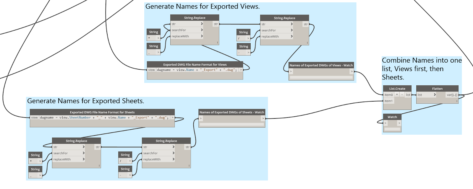
This post describes the nodes that generate the file names for the exported drawing files. As you may recall from the previous posts in this series, a list of Views and Sheets was generated from a user-created ViewSheetSet in Revit® by a Python Script node. That list was then separated into two lists, one for Views and one for Sheets, to allow for separate naming conventions for the exported drawing files for each. (Specifically, so that the sheet number can be included in the file name for Sheets.) The nodes that do this are contained in three groups: Generate Names for Exported Views, Generate Names for Exported Sheets and Combine Names....
All three groups make use of out-of-the-box nodes. The first two groups are nearly identical, and can be described simultaneously. The first node in each of those groups is a Code Block node, renamed to Exported DWG File Name Format for Views for the exported Views and Exported DWG File Name Format for Sheets for the exported Sheets. Each of these nodes has one input, view which takes the respective list from the List.FilterByBoolMask node covered in Part 3. A combination of parameter values associated with each View/Sheet and text is used to create the file name for each View/Sheet:
  • For Views: dwgname = view.Name + "_Export" + ".dwg";
  • For Sheets: dwgname = view.SheetNumber + "_" + view.Name + "_Export" + ".dwg";
The drawing name for Views concatenates the view.Name parameter value with "_Export" and the ".dwg" file extension. The drawing name for Sheets is similar, but adds the view.SheetNumber parameter values at the beginning, separating the sheet number from the sheet name with an underscore ("_") character. This is what I set up as a default for use in my office; you can customize this to meet your needs by adding, removing or rearranging the parts.

The lists of Sheet and View names are then run through two String.Replace nodes. The first replaces any asterisks ("*") with underscores ("_") and the second replaces any forward slashes ("/") with hyphens ("-"), as neither of these characters are permitted in a drawing file name, even though they are allowed in a View or Sheet name in Revit. Each resulting list of file names is then passed through a Watch node, so that the contents can be inspected after the graph is run. These two lists are then sent to the Combine Name... group, where a List.Create node and a Flatten node combine them into a single list. An optional Watch node is included here, as well.

So now we have a combined list of View and Sheet objects (from Part 3) and a combined list of file names for the corresponding exported files. The next post will look at the remaining user input nodes.

Next post in this series [Part 5]

September 01, 2018

Dynamo: Export Views and Sheets from Revit - Part 3

First post in this series [Part 1]
Previous post in this series [Part 2]

This post describes the nodes used to separate the Views from the Sheets that were obtained from the ViewSheetSet that the user specified as the source of Views and/or Sheets to be exported. This Dyanmo graph generates file names for the exported Views/Sheets. In order to be able to use the Sheet Number in the file name of exported Sheets, Views and Sheets need to be processed separately when generating the file names as Views do not have a Sheet Number parameter, so that cannot be part of the name generation code for Views. Separating the Views from the Sheets in two separate lists and processing each list separately when generating the file name seemed like the easiest way to handle that.

As noted in Part 2, the Python Script 1 node generates a list of View and Sheet objects, based on those included in the ViewSheetSet specified by the user. In order to separate that list into two separate lists, the List.FilterByBoolMask node is used. That requires a Boolean Mask, which is a list of true and false values. Items in the original list whose index corresponds to a true in the Mask list end up in the "in" output list. Those that correspond to false become part of the "out" list. The nodes in the lower left corner of the image above generate the Boolean Mask:
  • The list of Views/Sheets in the Set are fed into the "element" input of a Element.GetParameterValueByName node.
  • A String node provides the input to the "parameterName" input, with a value of "Category".
  • This creates a list of category objects, representing the category of the items in the View/Sheet list.
  • That list of categories is converted to a list of strings, representing the name of each category by the Element.Name node.
  • This list of strings is then passed to the Equal x to y? operator node (==), as the "x" input.
  • The "y" input is provided by a String node, with the value "Views".
  • The output will be a list of true/false values, based on whether the category name is "Views". Any Views on the original list will have a true value, and any Sheets will have a false value on that list.
Feeding the original list of Views/Sheets into the "list" input of the List.FilterByBoolMask node and the Bool Mask we just created above into the "mask" node will send the Views to the "in" output and the Sheets to the "out" output. These are sent to the respective file name generation nodes, to be covered in the next post in this series.

But before closing, there are two additional nodes in the blue node group in the image above. Eventually, we need to export the Views and/or Sheets, so we need to recombine the separated lists. I chose to put the Views first and the Sheets second, and used a List.Create node to combine the two. The List Create node will generate a list with two sublists, one of the Views and one of the Sheets. I just want a single combined list, which the Flatten node creates.

Note also that it is perfectly acceptable for the ViewSheetSet to have only Views or only Sheets. The nodes above will still generate two separate lists; one will just be empty.

Next post in this series [Part 4]

August 10, 2018

Dynamo: Export Views and Sheets from Revit - Part 2

First post in this series [Part 1]

This post will cover the part of the graph that gets the list of Views and/or Sheets from a user-selected ViewSheetSet that are to be exported.
As noted in Part 1, the user has to create a View/Sheet Set in Revit® and add all of Views and/or Sheets to be exported to that set. The user enters the name of that set into a string node, labeled ViewSheetSet Name - String in the green-colored group labeled 2. Enter Name of Set to Export. Just above that, the Element Types node is set to the ViewSheetSet type, which is then fed to the All Elements of Type node to get a list of all of the ViewSheetSet objects in the active project. This list of ViewSheetSet objects is passed to the Element.Name node, which generates a list of the names (as strings) of those ViewSheetSets. This list is passed to the IndexOf node, along with the name that the user entered, to determine the index of that name on the list. Finally, the list of ViewSheetSets and the index of the desired ViewSheetSet are passed to the List.GetItemAtIndex node, to get that ViewSheetSet object.

During my initial testing, I passed the ViewSheetSet object to an Element.Parameters node, to see what information could be obtained from the object. The list of Views/Sheets included in that ViewSheetSet was not found there, so this node need not be included in the final graph. It turns out that there is not a node that ships with Dynamo that will generate a list of Views/Sheets that are included in a ViewSheet Set, and I was not able to find one in any of the third-party packages I have installed. I was able to find this thread in the DynamoBim.com Forum, in which Kulkul posted the Python code needed to extract a list of the Sheets/Views. My adaption of that, shown in the image below, is the code behind the Python Script 1 node, which takes the desired ViewSheetSet object as input and generates a list of the included Views and Sheets as output.

That list of Views and Sheets is then sent to several locations. During development, I added an Element.Name node and two Watch nodes to view the list. These do not need to be part of the final graph, but I left them in as a way to visually check that the correct ViewSheetSet was obtained.

In the next installment, I will cover the nodes that separate the list of Views/Sheets into separate lists of Views and Sheets. I wanted to do this so that I could include the Sheet Number value as part of the name of exported Sheets. Since Views do not have a Sheet Number property, they needed have the name of the exported drawing generated separately.

Next post in this series [Part 3]

July 10, 2018

Dynamo: Export Views and Sheets from Revit - Part 1

I had a request the other day to streamline the process of updating CAD Exports for an Autodesk Revit® project. Unfortunately, some team members are not working in Revit, so certain Views have to be exported to CAD on a regular basis for use as backgrounds for the non-Revit-using team members. After a bit of trial (and a little tribulation) along with an enormous amount of help from the generous souls who have posted sample code to the Community Forums at dynamobim.org, I came up with the following Dynamo graph. All of the nodes used are "out-of-the-box" nodes available in the 1.3.2 version of Dynamo, but there are two Python Script nodes, the code for which is based on example code posted in the Community Forums. (As always, click on a image to see a full-size version of the image.)

The end user has to do three things prior to using the graph:
  • Create a View/Sheet Set into which all of the Views and/or Sheets to be exported are placed.
  • Get the name of the DWG Export Setup to be used for the export. (Create a new one if required by the project.)
  • Identify the folder (with full path) where the exports are to be sent.
With that information in hand, the user can make a project-specific copy of the Dynamo file, enter those three items in the appropriate nodes, save the file, and then run it whenever updated exports are needed. Dynamo will overwrite any files of the same name in the target folder, so previous versions need to be archived elsewhere if a record of all exports is required. In the next few posts, I will go through the various sections of the graph, and, to the best of my ability, explain how each works, including the two Python Script nodes that do the heavy lifting. Before doing so, I would like to thank the following Community Forum contributors whose helpful responses to others' questions also helped me to complete this project.
  • Konrad K Sobon, for the code in the Python Script 2 node that does the exporting, as well as for the advice given to Andrea_Ghensi in the same thread regarding code to have a specific DWG Export Setup used for the export. See the full thread here.
  • Andrea_Ghensi, for the code in the Python Script 2 node that allows the user to specify an existing DWG Export Setup for the export (as amended by Konran K Sobon). See the same thread as the previous link.
  • 4bimfercesp, for the line in the code in the Python Script 2 node that allows the user to specify whether Views on a Sheet should be merged into the exported sheet or exported as a separate file that is externally referenced into the exported Sheet file. See the full thread here.
  • Kukul, for the code in the Python Script 1 node that extracts a list of the Views/Sheets in a View/Sheet Set. See the full thread here.
The nodes at the left side of the graph that are in green-colored groups are the nodes that require user input. I will conclude this first post with one of the simpler parts of the graph, the Folder for Exported DWGs - Directory Path node.
This is an instance of the out-of-the-box Directory Path node, with a modified node title. The Browse button allows the user to navigate to the folder where the exported drawings are to be placed. The output of this node is fed to the IN[0] input of the Python Script 2 node. One thing to note about this node, and the other user input nodes, is that if you right click on the node, you will see that the Is Input item on the context menu is checked. That means that this node will be available for user input in Dyanmo Player.

I am not certain how many clicks using this graph will save over manually doing the same export (probably a few on subsequent exports if Dynamo Player is used, without making any changes to the inputs), but it certainly will help make the process more consistent.

Next post in this series [Part 2]

March 14, 2018

Civil 3D 2018 to ACA 2013

We have started to get drawings from Civil consultants in the 2018 file format. Thanks to our recent move to the AEC Collection, we now have access to AutoCAD® Civil 3D®. I have no idea how to use that program, beyond the AutoCAD basics, but I installed the 2018 version of it in the hope that I would be able to export the received drawing to "vanilla" AutoCAD®. Similar to AutoCAD® Architecture and AutoCAD® MEP, you can go to the Application Menu > Export > Export Civil 3D Drawing to export a drawing. There is a dialog, where you can choose between AutoCAD DWG and Microstation® DGN, and, for DWG export, the Export Settings allow you to select a file format, such as 2013.

I did all of that, and Civil 3D did its thing, and drawings were generated. (I got more than one because I left the Include sheets toggle checked, so a drawing for each layout was also generated.) I fired up AutoCAD Architecture 2016 and opened the exported "Model" file, only to be greeted by this dialog:
What?! I just exported this file to a previous file format - there should not be ANY AEC objects, let alone future ones. I closed the dialog and tried run the WALLADD command. No dice - "Command not allowed because drawing contains objects from a newer version of this application." appeared at the command line. So this drawing, supposedly exported to the previous file format, can be opened, but is otherwise mostly useless. You can externally reference the file and use AEC commands in the host file, saving it from being totally useless.

Still, I expected to have a "clean" 2013-format file that only has non-AEC AutoCAD objects. I tried a Window selection in Model Space to get all the visible objects and then tried to copy them to the clipboard, hoping that if I pasted them in a new file, the future AEC Objects would not come along for the ride. That did not work, as the copy to clipboard failed.
Then I tried to select the Model Space objects and use the WBLOCK command, again hoping that the future AEC Objects would be left behind. That also failed.
Finally, I opened the file in AutoCAD Architecture 2018 and tried to use the AECEXPORTTOAUTOCAD2013 command, in the somewhat desperate hope that might work. I got the following dialog indicating that an error had occurred during the save.
And then this dialog showed up, to rub salt into the wound. I tried "saving" as AutoCAD-only objects!
This was followed by a second showing of the warning dialog recommending the use of the RECOVER command. Opening this file in AutoCAD Architecture 2016 resulted in the same Open Drawing - New Versions of Objects in Drawing dialog as shown in the first image above.

Finally, I tried starting a new drawing and using the INSERT command to insert the originally exported "Model" drawing file. I received the following dialog:
The small-print statement "Newer AEC objects will be disallowed from participating in this operation" gave me hope, as it was not flat-out refusing to do the insertion, and I did not want the newer objects in the file. That hope was confirmed, as it did insert what appeared to be all of the objects that were visible in the exported file, and I was able to add AEC objects to the file. Upon saving and reopening, there were no dialogs chastising me for having a file with future AEC Objects in it. Success! I still think that the original export should have been AEC-object-free, and object to having to go to the extra step of inserting the exported file into an empty file to get rid of the future objects, but at least I have a workaround for providing a "clean" file in the 2013 format that does not require proxy objects or object enablers.

December 16, 2015

Revit: CAD Export Layer Mapping - Restore Subcategory Default

When editing a DWG/DXF Export Setup, you may have noticed that some subcategories have the layer name of the main category, enclosed in curly braces ("{" and "}") and italicized, and, if you change the layer name of the main category, these all automatically update to match that change in the main category. For example, using the Revit 2014 out-of-the-box US Imperial default.rte template, the Doors category looks like this:

Notice that the Elevation Swing and Plan Swing subcategories have { A-DOOR } in the Layer column, whereas the Panel subcategory just has A-DOOR. If the layer for the Doors main category is changed, the Elevation Swing and Plan Swing subcategories also change, but the Panel subcategory does not.

If you want a subcategory to be linked to the main category name, but it is not already so linked, you can do one of the following:
  • If there is already another subcategory so linked, you can copy the text in that subcategory, and then paste that value into the subcategory you wish to link. Be certain to copy the entire string, including the leading space characters.
  • If there is not already a linked subcategory, or you just prefer typing to cutting and pasting, type two space characters, an opening curly brace ("{"), one space character, the layer name as it currently appears in the main category, one space character and a closing curly brace ("}"). Once you press the ENTER key or click into another field, the text will italicize, letting you know you entered it correctly.
  • You can also just type two space characters, an opening curly brace ("{"), two space characters and a closing curly brace ("}") in the subcategory's Layer field, and then make a change to the main category's layer name, if that is easier for you. After you change the main categories layer name, you can change it back if you did not want to make a change to it.
As always, click on an image to see a larger version of it.