The oh-so-considerate union leadership called a strike at 3 am on Election Day (yesterday, November 3), giving commuters (including me) no opportunity to make alternate arrangements and squandering any sympathy those same commuters might have had for the strikers. Thanks to the intervention of the governor and the mayor, the strike was postponed until after those rich enough to afford World Series tickets but too cheap to pay for parking at the stadium were able to get home from Game 5 in Philadelphia. So those who only ride public transit when the Phillies make it to the World Series were accommodated; those who ride every day were [insert expletive of your choice here].
I now find myself with a 6-mile walk each way, in and out of work. The good news is I have been able to do it in 90 minutes (average rate of 4 mph!), which is much faster than I would have estimated. The bad news is my commuting time is now about two hours longer than it was, and my schedule needs to adjust accordingly. As such, it is unlikely I will have time to post much to this blog until such time as the transit strike is resolved. As of Day 2, no additional talks have taken place (or even been scheduled).
November 04, 2009


October 26, 2009
Equal Lights Republished
A little over a year ago, I contributed an article to the AU Quarterly Newsletter on creating equal lights in Door/Window Assemblies, Curtain Walls and Curtain Wall Units. Unfortunately, when the AU Online site was overhauled last December, the links to articles from previous newsletters were lost. For those who never read the article and those who have forgotten its contents (including me), here is the article. If you are interested, a drawing file that has the Door/Window Assemblies used to generate the images below, along with some other experiments done while writing the article, can be found in this post in the AutoCAD Architecture Content Discussion Group.
Equal Light Openings With Door/Window Assemblies and Curtain Wall Units
You might think that creating Door/Window Assembly or a Curtain Wall that has equal light openings is a fairly simple task – set up a Division with a fixed number of Cells and you should be good to go. The same technique should also work if you wanted to use a Curtain Wall Unit to subdivide those equal Cells with “muntins” to get equal light openings between muntins. You could then place the Door/Window Assembly or Curtain Wall at any size and have equal light openings. While you can achieve the desired results, it will take a little knowledge and some additional effort.
There are two reasons why it is not quite as simple as we might like:

If you keep the above in mind, it is possible to create equal light openings, and we will take a look at some techniques to do so, starting with the outer Door/Window Assembly or Curtain Wall, and then looking at the impact those choices have on a nested Curtain Wall Unit. A Door/Window Assembly will be used for these examples, but the techniques also apply to Curtain Walls.
There are several ways to generate equal light openings in the parent Door/Window Assembly or Curtain Wall.

For a Simple Panel, Door or Window Infill, using the Start/End Division Offset method is the way to go, as these elements will be sized to fit the light opening of the Cell in which they are placed. If you can achieve your desired Muntin pattern by using the Muntins in a Window Style, that may be the best way to get equal light openings in a style that works for any overall Frame dimension, using a single Infill style.

If you need the greater control over spacing that using a Curtain Wall Unit for Infill can provide, there is a small problem with using the Start/End Offset method – the applied offset makes the outer Cells wider, but does not move the grid lines from the outside edge of the Frame, so the same Curtain Wall Unit Style can not be used for all Cells. (The Mullion Offsets method may also have the same problem, because the light opening is likely not centered on the gridlines in all of the Cells.) Fortunately, two copies of that Curtain Wall Unit Style, one with a Division Start Offset and one with a Division End Offset equal to the Offsets applied to the parent object can be quickly created, assigned to an Infill and used in the Start Cell and End Cell respectively. This gives you the look you want, while maintaining the flexibility of being able to change the overall Door/Window Assembly dimensions.

Here is an example of a more complex muntin pattern. A series of nested grids, all using a fixed number of Cells, was used to create the pattern. Start and or End Offsets were applied as needed to get the equal light openings shown. This can be a little tricky to set up, since the nested grids for the Start and End Cells also need to have offsets applied, but once you have it set up, you can create a Door/Window Assembly with any overall length and height and maintain equal light openings.

Equal Light Openings With Door/Window Assemblies and Curtain Wall Units
You might think that creating Door/Window Assembly or a Curtain Wall that has equal light openings is a fairly simple task – set up a Division with a fixed number of Cells and you should be good to go. The same technique should also work if you wanted to use a Curtain Wall Unit to subdivide those equal Cells with “muntins” to get equal light openings between muntins. You could then place the Door/Window Assembly or Curtain Wall at any size and have equal light openings. While you can achieve the desired results, it will take a little knowledge and some additional effort.
There are two reasons why it is not quite as simple as we might like:
- The “equal” in equal Cells refers to the distance between grid lines. Unless offsets are applied to the Frame or Mullion, the outer grid lines occur at the outside edge of the Frame, while the inner grid lines are centered on the Mullions. This means that the light opening of the start and end Cells will be reduced by the full width of the Frame, plus half the width of a Mullion, while interior Cells will only be reduced by the width of a Mullion. If both Frame and Mullion are the same width, the Start and End Cells’ light opening will be less than the light opening of the Middle Cells.
- The grid lines of a nested Curtain Wall Unit are spaced evenly, based on the location of the parent Door/Window Assembly or Curtain Wall grid lines bounding that Cell, not on the light opening of that Cell. The Frame of the Curtain Wall Unit will be located at the light opening of the Cell, but the locations of “equal Cell” Mullions may not generate equal light openings in the Start, End, Top or Bottom Cells.

Figure 1
Equal Cell Door/Window Assembly with Equal Cell Curtain Wall Unit Infill
Blue Dimensions – Gridlines; Red Dimensions – Light Openings (Typical in all Figures)
Equal Cell Door/Window Assembly with Equal Cell Curtain Wall Unit Infill
Blue Dimensions – Gridlines; Red Dimensions – Light Openings (Typical in all Figures)
If you keep the above in mind, it is possible to create equal light openings, and we will take a look at some techniques to do so, starting with the outer Door/Window Assembly or Curtain Wall, and then looking at the impact those choices have on a nested Curtain Wall Unit. A Door/Window Assembly will be used for these examples, but the techniques also apply to Curtain Walls.
There are several ways to generate equal light openings in the parent Door/Window Assembly or Curtain Wall.
- Frame Offset: This might be acceptable for a Curtain Wall, since it does not create its own opening, although the Curtain Wall’s overall length and height will not represent the overall Frame dimension. For Door/Window Assemblies that are anchored in a Wall, offsetting the Frame pushes it into the Wall, leaving part of the Frame buried in the Wall, which is not acceptable.
- Mullion Offsets: By creating multiple Mullions with varying offsets, assigned to the proper locations, equal light openings can be created. For example, three equal openings can be created when the Frame and Mullion widths are equal by setting up a vertical Division with three equal Cells and then creating two Mullions, each offset by 1/6 of their width toward the middle, resulting in each Cell losing 1-1/3 of the Frame/Mullion width. This can get rather complex when there are five or more equal openings to be created.
- Start/End Division Offsets: This is the easiest method, and can also accommodate the case where the Frame and Mullion dimensions are not equal. Simply subtract one half the width of the Mullion from the Frame width and use that for both the Start Offset and the End Offset of the Division. This will make the Start and End Cells wider than the Middle Cells, resulting in equal light openings no matter how many Cells are specified, without the need to create offset Mullions.

Figure 2
Equal Cell Door/Window Assembly with 1.5 Start and End Offset
Equal Cell Door/Window Assembly with 1.5 Start and End Offset
For a Simple Panel, Door or Window Infill, using the Start/End Division Offset method is the way to go, as these elements will be sized to fit the light opening of the Cell in which they are placed. If you can achieve your desired Muntin pattern by using the Muntins in a Window Style, that may be the best way to get equal light openings in a style that works for any overall Frame dimension, using a single Infill style.

Figure 3
Equal Cell Door/Window Assembly with 1.5 Start and End Offset
Window Style Infill with 0 Width Frame and 1 Width Sash and Muntins
Equal Cell Door/Window Assembly with 1.5 Start and End Offset
Window Style Infill with 0 Width Frame and 1 Width Sash and Muntins
If you need the greater control over spacing that using a Curtain Wall Unit for Infill can provide, there is a small problem with using the Start/End Offset method – the applied offset makes the outer Cells wider, but does not move the grid lines from the outside edge of the Frame, so the same Curtain Wall Unit Style can not be used for all Cells. (The Mullion Offsets method may also have the same problem, because the light opening is likely not centered on the gridlines in all of the Cells.) Fortunately, two copies of that Curtain Wall Unit Style, one with a Division Start Offset and one with a Division End Offset equal to the Offsets applied to the parent object can be quickly created, assigned to an Infill and used in the Start Cell and End Cell respectively. This gives you the look you want, while maintaining the flexibility of being able to change the overall Door/Window Assembly dimensions.

Figure 4
Equal Cell Door/Window Assembly with 1.5 Start and End Offset
Curtain Wall Unit Style Infill – Three Similar Styles:
1.5 Start Offset in Start Cell, No Offsets in Middle Cell, 1.5 End Offset in End Cell
(3.5 Offset Top and Bottom at Horizontal Division, All Three Styles)
Equal Cell Door/Window Assembly with 1.5 Start and End Offset
Curtain Wall Unit Style Infill – Three Similar Styles:
1.5 Start Offset in Start Cell, No Offsets in Middle Cell, 1.5 End Offset in End Cell
(3.5 Offset Top and Bottom at Horizontal Division, All Three Styles)
Here is an example of a more complex muntin pattern. A series of nested grids, all using a fixed number of Cells, was used to create the pattern. Start and or End Offsets were applied as needed to get the equal light openings shown. This can be a little tricky to set up, since the nested grids for the Start and End Cells also need to have offsets applied, but once you have it set up, you can create a Door/Window Assembly with any overall length and height and maintain equal light openings.

Figure 5
Equal Cell Door/Window Assembly with 1.5 Start and End Offset
Curtain Wall Unit Style Infill with Offsets Applied to Multiple Divisions as Necessary
Equal Cell Door/Window Assembly with 1.5 Start and End Offset
Curtain Wall Unit Style Infill with Offsets Applied to Multiple Divisions as Necessary
October 20, 2009
Revit - Modify Group Origin
This will likely not be news to long-time Revit users, but after a couple of months of Revit use, I discovered this feature today. The project on which I am working has a number of pairs of identical patient rooms, which another team member set up as Model Groups. The rooms are arranged along the curved exterior of the building, so each group is rotated slightly from the adjacent groups. After working through several design iterations, I was trying to get the "final" design drawn accurately and to get the adjoining Walls to clean up correctly. I was frustrated by the lack of an exposed coordinate system or the equivalent of an insertion point in Revit. I also found it annoying that I had to continually repostition the rotation point when orienting each Model Group.
It turns out that there is an "origin" for Model Groups and that origin is the default rotation point for the group. Somewhere along the line, the origin of our Model Group got moved off to a random point within one of the rooms. Fortunately, it is quite easy to relocate the origin point. (Which probably explains how it got moved to such a strange place - it is almost too easy to move it.) Simply select an instance of the Model Group in a Plan or 3D view. As shown in the image below, in a Plan view you will get two axes, labeled "X" and "Y", with three grip points. Click on the grip point at the intersection of the axes... ...and drag the grip...
 ...to the point where you want the origin placed and release the left mouse button.
 I used an intersection snap [SI] in the example in the screen captures to be certain it was placed accurately. The grips at the "arrow ends" of the axes allow you to rotate the axes, if you want to change the angle at which the Model Group initially inserts.
One small step on the road to Revit enlightenment; one giant reduction in frustration.
It turns out that there is an "origin" for Model Groups and that origin is the default rotation point for the group. Somewhere along the line, the origin of our Model Group got moved off to a random point within one of the rooms. Fortunately, it is quite easy to relocate the origin point. (Which probably explains how it got moved to such a strange place - it is almost too easy to move it.) Simply select an instance of the Model Group in a Plan or 3D view. As shown in the image below, in a Plan view you will get two axes, labeled "X" and "Y", with three grip points. Click on the grip point at the intersection of the axes...
 ...and drag the grip...
 ...to the point where you want the origin placed and release the left mouse button.
 I used an intersection snap [SI] in the example in the screen captures to be certain it was placed accurately. The grips at the "arrow ends" of the axes allow you to rotate the axes, if you want to change the angle at which the Model Group initially inserts.
One small step on the road to Revit enlightenment; one giant reduction in frustration.
October 01, 2009
Revit Praise #1 - Parametric Families
Today was a really, really bad Revit day, but it would be churlish of me to say only bad things about Revit® Architecture, when that does not reflect my opinion of the software on most days. I realize that much of my struggle can be ascribed to a combination of my inexperience with the software, the overly demanding nature of the geometry of the building for which the fitout is being done and "issues" with the linked Revit files for the building, done by another firm and outside of my ability to control or improve.
So lets focus on a strength of Revit that I find quite fascinating: the ability to create custom components that are driven by parameters. This past August I had the good fortune to be able to take Paul Aubin's on-line Mastering the Family Editor, a series of five one-hour, on-line training sessions covering the use of Revit's Family Editor. (See Paul's website for current offerings. It was my understanding that he plans to make recordings of sessions available, for a fee, to those who did not sign up for the live course, but I did not see a link for this particular course as of tonight.) By setting up parameters, you can get the same graphics to "flex" to multiple sizes ("types", in Revit terminology) without the need to create multiple styles, as you would with a Multi-View Block in AutoCAD® Architecture.
Armed with that excellent knowledge, I was able to create two families for accessible shower seats (one each for rectangular and L-shaped). Each family currently has two types - one for the maximum seat size allowed under ICC/ANSI A117.1 and one for the minimum size. The images below show the plan views for the two families. The origin point for the component is at the upper left corner. The green dashed lines are "reference planes", and the top and far left ones are designated as defining the component's origin (the corner of a shower). The reference planes do not show when the object is placed in a project, but within the family, provide a framework on which the 2D linework (used here, to keep file size down) or 3D objects can be locked.

The dimensions with text are the parameters and in this case are all type-based. Each type created can set a different value for each of these dimensions. The dimensions with numbers only are fixed dimensions, which maintain desired distances between two reference planes when one is moved by a change in a parameter value. In this case, I chose to make the maximum allowable distance off the back and side walls fixed dimensions.
The blue double arrow icons are controls that allow the graphics to be "flipped" to cover opposite hand situations. Adding these is as simple as selecting the Control tool on the Design bar, choosing the Control type on the Options Bar and clicking in the plan view window to place the Control. (I am currently using Revit Architecture 2009; the process in 2010 may be slightly different.)
One might argue that with only two types in each family, this is a bit of overkill. Other types, based on specific manufacturer's dimensions, could easily be added. (The elevation views also have a Height and Thickness parameter to drive the location of the top of the seat and the thickness of the seat.) The point here is to show some of the possibilities. Components that have the same basic shape, but many possible sizes - for example, Doors - allow a single piece of content to have many types, representing the range of available sizes. By carefully setting up reference planes and parameters, you can add as much control to your custom content as you need, rather than having to make a custom Profile or View Block for each size or live with having a single Profile or View Block being scaled to the overall width/height, as you would have to do in Architectural Desktop.
Using type parameters allows you to build-in standard sizes, which is appropriate for items that are manufactured to certain, predetermined sizes. Parameters can also be made instance-based, if you want to be able to set the parameter value for each instance, which would be appropriate for content that is built-to-order.
So lets focus on a strength of Revit that I find quite fascinating: the ability to create custom components that are driven by parameters. This past August I had the good fortune to be able to take Paul Aubin's on-line Mastering the Family Editor, a series of five one-hour, on-line training sessions covering the use of Revit's Family Editor. (See Paul's website for current offerings. It was my understanding that he plans to make recordings of sessions available, for a fee, to those who did not sign up for the live course, but I did not see a link for this particular course as of tonight.) By setting up parameters, you can get the same graphics to "flex" to multiple sizes ("types", in Revit terminology) without the need to create multiple styles, as you would with a Multi-View Block in AutoCAD® Architecture.
Armed with that excellent knowledge, I was able to create two families for accessible shower seats (one each for rectangular and L-shaped). Each family currently has two types - one for the maximum seat size allowed under ICC/ANSI A117.1 and one for the minimum size. The images below show the plan views for the two families. The origin point for the component is at the upper left corner. The green dashed lines are "reference planes", and the top and far left ones are designated as defining the component's origin (the corner of a shower). The reference planes do not show when the object is placed in a project, but within the family, provide a framework on which the 2D linework (used here, to keep file size down) or 3D objects can be locked.

Square Shower Seat

L-Shaped Shower Seat
(Click on any image to see a full-size version; use the back button in your browser to return here)
(Click on any image to see a full-size version; use the back button in your browser to return here)
The dimensions with text are the parameters and in this case are all type-based. Each type created can set a different value for each of these dimensions. The dimensions with numbers only are fixed dimensions, which maintain desired distances between two reference planes when one is moved by a change in a parameter value. In this case, I chose to make the maximum allowable distance off the back and side walls fixed dimensions.
The blue double arrow icons are controls that allow the graphics to be "flipped" to cover opposite hand situations. Adding these is as simple as selecting the Control tool on the Design bar, choosing the Control type on the Options Bar and clicking in the plan view window to place the Control. (I am currently using Revit Architecture 2009; the process in 2010 may be slightly different.)
One might argue that with only two types in each family, this is a bit of overkill. Other types, based on specific manufacturer's dimensions, could easily be added. (The elevation views also have a Height and Thickness parameter to drive the location of the top of the seat and the thickness of the seat.) The point here is to show some of the possibilities. Components that have the same basic shape, but many possible sizes - for example, Doors - allow a single piece of content to have many types, representing the range of available sizes. By carefully setting up reference planes and parameters, you can add as much control to your custom content as you need, rather than having to make a custom Profile or View Block for each size or live with having a single Profile or View Block being scaled to the overall width/height, as you would have to do in Architectural Desktop.
Using type parameters allows you to build-in standard sizes, which is appropriate for items that are manufactured to certain, predetermined sizes. Parameters can also be made instance-based, if you want to be able to set the parameter value for each instance, which would be appropriate for content that is built-to-order.
September 30, 2009
Revit Rant #2
The project on which I am working has a Model Group for a pair of patient rooms, which is then repeated multiple times on two floors.
When making changes to the Model Group, you enter a special mode. When the edits are done, you "Finish", and the edits are propogated to each instance of the Model Group. When it works, it is really great, and most of the time it works.
Today, I ran into a problem that I had encountered previously. There is another team member working on the project, and when I tried to save the changes I made to the Model Group, I got an error message stating that the other person had possession of an element that needed to change as part of my Model Group save. The error message indicated that the other person needed to Save to Central, and then I needed to Reload Latest.
Getting the other person to Save to Central was no problem, since we sit in adjacent cubicles. Unfortunately, the Reload Latest function is disabled when editing a Model Group, so I still can not save the Model Group changes! That in itself is infuriating (I just love redoing work), but to have the error message tell me to do something that can not be done is simply rubbing salt in the wound.
So, you need to strike a balance between saving Model Group changes so often that you waste too much time waiting for the save to occur and doing so much work in a Model Group edit session that, should you be unable to save because you can not Reload Latest, you lose too much time discarding and redoing the edits.
When making changes to the Model Group, you enter a special mode. When the edits are done, you "Finish", and the edits are propogated to each instance of the Model Group. When it works, it is really great, and most of the time it works.
Today, I ran into a problem that I had encountered previously. There is another team member working on the project, and when I tried to save the changes I made to the Model Group, I got an error message stating that the other person had possession of an element that needed to change as part of my Model Group save. The error message indicated that the other person needed to Save to Central, and then I needed to Reload Latest.
Getting the other person to Save to Central was no problem, since we sit in adjacent cubicles. Unfortunately, the Reload Latest function is disabled when editing a Model Group, so I still can not save the Model Group changes! That in itself is infuriating (I just love redoing work), but to have the error message tell me to do something that can not be done is simply rubbing salt in the wound.
So, you need to strike a balance between saving Model Group changes so often that you waste too much time waiting for the save to occur and doing so much work in a Model Group edit session that, should you be unable to save because you can not Reload Latest, you lose too much time discarding and redoing the edits.
Revit Rant #1
DISCLAIMER: It may very well be that the issues discussed below have a solution, of which I am unaware, due to my current level of Revit experience.
I am finding it very difficult to draw/model with any accuracy. The lack of an exposed coordinate system (let alone a user-defined one), and simple things like insertion points for linked Revit files or Model Groups is maddening. Modeling anything, in place, where you want it when you first place it is extremely difficult. The fact that the project on which I am working has multiple weird angles does not help.
I am also frustrated by the number of items in the program that can not be done with accuracy or repeatably. Clipping a view and placing a view on a sheet are, so far as I can tell, a total "eyeball" situation. It becomes rudely apparent when you change from one sheet to another, and what should be aligning plans on adjacent floors (or aligning plans of different types of the same floor) ends up being an animation, with the plan moving up and down, side to side or both.
Side Note to Self: The next time someone asks me to work on a project where adjacent rooms are rotated at 1.53 degrees, just say no.
I am finding it very difficult to draw/model with any accuracy. The lack of an exposed coordinate system (let alone a user-defined one), and simple things like insertion points for linked Revit files or Model Groups is maddening. Modeling anything, in place, where you want it when you first place it is extremely difficult. The fact that the project on which I am working has multiple weird angles does not help.
I am also frustrated by the number of items in the program that can not be done with accuracy or repeatably. Clipping a view and placing a view on a sheet are, so far as I can tell, a total "eyeball" situation. It becomes rudely apparent when you change from one sheet to another, and what should be aligning plans on adjacent floors (or aligning plans of different types of the same floor) ends up being an animation, with the plan moving up and down, side to side or both.
Side Note to Self: The next time someone asks me to work on a project where adjacent rooms are rotated at 1.53 degrees, just say no.
September 14, 2009
Update 1 for ACA 2010 Released
 Update 1 for AutoCAD® Architecture 2010 was released today. Get the proper version for your operating system type (32-bit or 64-bit). Be certain to read the "readme" before installation, where you will find installation instructions as well as a summary of the AEC and AutoCAD issues resolved.
September 05, 2009
2010 File Format Change
This post may be somewhat on the late side, but given the continuing confusion in the Discussion Groups, it may still be of value to some. The 2010 release of AutoCAD® and the related "vertical" products, such as AutoCAD® Architecture, introduced a new AutoCAD file format (the 2010 format). ACA files created in 2010 as well as files created in a previous release and opened and saved in 2010 will have 2010-format AEC objects, which are NOT compatible with previous releases and CANNOT be saved back to a previous release format.
As this Knowledge Base article states, there are only two options for going back to a previous release. Exporting to AutoCAD will explode all AEC objects to AutoCAD objects. SaveAs to a previous release will result in un-editable proxy objects representing the AEC objects and new AEC objects will NOT be able to be created in the file.
So, if you need editable AEC objects, there is no going back from a 2010-format file to an earlier release. Keep that in mind when planning a deployment of ACA 2010. And, for the record, this is exactly the same situation as occurred with the release of ADT 2004 and ADT 2007.
As this Knowledge Base article states, there are only two options for going back to a previous release. Exporting to AutoCAD will explode all AEC objects to AutoCAD objects. SaveAs to a previous release will result in un-editable proxy objects representing the AEC objects and new AEC objects will NOT be able to be created in the file.
So, if you need editable AEC objects, there is no going back from a 2010-format file to an earlier release. Keep that in mind when planning a deployment of ACA 2010. And, for the record, this is exactly the same situation as occurred with the release of ADT 2004 and ADT 2007.
August 28, 2009
Another Automatic Property Override Sample
For those of you who never tire of examples of using a manual property and a formula property to allow for overriding the value of either an automatic property or a style-based manual property on an object-by-object basis (and for those who have never seen an example of this), I have posted a ZIP file with a file created in AutoCAD® Architecture 2009 to the Default Finish Scheduling thread in the Autodesk AutoCAD Architecture Discussion Group. Look for the RoomFinishTest.zip file attached to my August 24, 2009 reply.
The sample file has a style-based Property Set with text-type manual properties for entering typical room finishes for a specific Space Style. If you set up separate Space Styles for each room type you have anyway, doing this provides an easy way to get schedulable finish information into your drawings, since you only need to enter the finish information once, in the Space Style, for each style. If your projects usually have the same finishes in all Spaces of the same type/style, the style-based Property Set could be all you would need. Even if you had two or three different sets of finishes for a particular Space type (for example, for offices), if there were a significant number of each office type, you would probably want to create a separate Space style for each office type, and assign the appropriate finishes at the style level.
Many projects will have individual Spaces that will have some variation from the typical finishes for its Space type. If there are only a few of these, it may not be too much trouble to create separate Space Styles for each variant. But if there are a large number of unique variants, creating a Space Style for each will quickly become a burden. Rather than give up on style-based properties and go to object-based properties (where you would need to enter the data for each individual Space), you can set up an object-based manual override property to hold a different value for just that one Space, and a formula property that you use in the Schedule Table, that checks to see if the override property is set to its default value. If so, the formula passes through the style-based typical value. If not, the formula passes throught the override value. That allows you to take advantage of the power of style-based properties without needing to create a separate Space Style for each variant.
The sample file has a handful of Space Styles and two custom Property Sets. The SpaceStyleFinishes Property Set contains five manual properties for entering the typical floor, base, wainscot, wall and ceiling finishes for a particular Space Style. Depending upon the nature of your work and the way you document finishes, you may need to add or subtract properties here; for example, you may want four wall finish properties (north, south, east and west). For the purposes of being able to create the example file without taking an inordinate amount of time, I limited the properties to those five. (As always, click on any image to see a full-size version; use the Back button on your browser to return here.) This Property Set applies to Space Styles and is attached to each style on the General tab, using the Property Sets... button.
 If you have a number of frequently used finishes, consider setting up a List Definition that applies to Manual Properties to hold the options for each finish type, then using that to speed entering values (and make them consistent). The sample file does not include this; values there were manually entered in the Edit Property Set Data dialog.
 The SpaceObjectFinishes Property Set contains two properties for each property in the style-based property: an Override property to hold the override value, when one is desired, and a formula property to pass through the appropriate value, as noted above.
 The default value for the override properties is "USEDEFAULT!" (without the quotation marks). The exact value you use is not important, so long as it is not anything that could be a value you would want to use for the override. The formula property for each finish type is similar to that shown below for the FloorFinish formula property.
The sample file also contains two Schedule Table Styles. One is meant for final documents, and shows only the "final" formula property value for each Space. You can not use the Cell Edit feature to edit the finish values in this Schedule Table, however, because automatic properties like formula properties can not be edited that way. If you prefer to make post-placement edits by using Cell Edit, then you will also want to have a "working" Schedule Table Style, which is the second one in the sample file. This lists the formula property, style-based typical property and object-based override property for each finish type. You can use Cell Edit on either the typical property, changing the formula property value for all instances of that style that do not have overrides, or the override property, changing the formula property value for just that Space.
 In the partial Schedule Table shown above, you can see that an override value has been entered for the floor finish for the last three Office Spaces (111, 112 and 113), changing the default value of CPT 2 to CPT 5.
The sample file has a style-based Property Set with text-type manual properties for entering typical room finishes for a specific Space Style. If you set up separate Space Styles for each room type you have anyway, doing this provides an easy way to get schedulable finish information into your drawings, since you only need to enter the finish information once, in the Space Style, for each style. If your projects usually have the same finishes in all Spaces of the same type/style, the style-based Property Set could be all you would need. Even if you had two or three different sets of finishes for a particular Space type (for example, for offices), if there were a significant number of each office type, you would probably want to create a separate Space style for each office type, and assign the appropriate finishes at the style level.
Many projects will have individual Spaces that will have some variation from the typical finishes for its Space type. If there are only a few of these, it may not be too much trouble to create separate Space Styles for each variant. But if there are a large number of unique variants, creating a Space Style for each will quickly become a burden. Rather than give up on style-based properties and go to object-based properties (where you would need to enter the data for each individual Space), you can set up an object-based manual override property to hold a different value for just that one Space, and a formula property that you use in the Schedule Table, that checks to see if the override property is set to its default value. If so, the formula passes through the style-based typical value. If not, the formula passes throught the override value. That allows you to take advantage of the power of style-based properties without needing to create a separate Space Style for each variant.
The sample file has a handful of Space Styles and two custom Property Sets. The SpaceStyleFinishes Property Set contains five manual properties for entering the typical floor, base, wainscot, wall and ceiling finishes for a particular Space Style. Depending upon the nature of your work and the way you document finishes, you may need to add or subtract properties here; for example, you may want four wall finish properties (north, south, east and west). For the purposes of being able to create the example file without taking an inordinate amount of time, I limited the properties to those five. (As always, click on any image to see a full-size version; use the Back button on your browser to return here.)
 This Property Set applies to Space Styles and is attached to each style on the General tab, using the Property Sets... button.
 If you have a number of frequently used finishes, consider setting up a List Definition that applies to Manual Properties to hold the options for each finish type, then using that to speed entering values (and make them consistent). The sample file does not include this; values there were manually entered in the Edit Property Set Data dialog.
 The SpaceObjectFinishes Property Set contains two properties for each property in the style-based property: an Override property to hold the override value, when one is desired, and a formula property to pass through the appropriate value, as noted above.
 The default value for the override properties is "USEDEFAULT!" (without the quotation marks). The exact value you use is not important, so long as it is not anything that could be a value you would want to use for the override. The formula property for each finish type is similar to that shown below for the FloorFinish formula property.
If "[FloorOverride]" = "USEDEFAULT!" Then
RESULT = "[SpaceStyleFinishes:FloorDefault]"
Else
RESULT = "[FloorOverride]"
End IfThe formula tests the override property to see if its value remains the default value. If so, it passes through the typical, style-based value. If not, it passes through the override value. By using this property in your Schedule Table Style and/or Schedule Tag, you get the advantages of both style- and object-based properties.The sample file also contains two Schedule Table Styles. One is meant for final documents, and shows only the "final" formula property value for each Space.
 You can not use the Cell Edit feature to edit the finish values in this Schedule Table, however, because automatic properties like formula properties can not be edited that way. If you prefer to make post-placement edits by using Cell Edit, then you will also want to have a "working" Schedule Table Style, which is the second one in the sample file. This lists the formula property, style-based typical property and object-based override property for each finish type. You can use Cell Edit on either the typical property, changing the formula property value for all instances of that style that do not have overrides, or the override property, changing the formula property value for just that Space.
 In the partial Schedule Table shown above, you can see that an override value has been entered for the floor finish for the last three Office Spaces (111, 112 and 113), changing the default value of CPT 2 to CPT 5.
August 23, 2009
AutoCAD® Architecture 2010 – UI Changes, Part 6 – The Ribbon, Render Tab
Render Tab
The Render tab is the fourth static (always available) tab provided in the out-of-the-box ACA CUI. The image below and all screen captures in this article are based on the shipping version.
Tools Panel
The Tools Panel contains a single button that toggles the tool palettes on and off, setting the Visualization tool palette group current when toggling it back on. If you would prefer that it simply switch to the Visualization tool palette group, refer to this previous article for instructions on how to modify the CUIX file.
Render Panel
The Render Panel contains commands related to rendering. The Render split button split button allows you to render or render a region.
 The main button will change to run the most recently chosen option from the drop-down list. The Render Presets drop-down button offers a list of named, pre-established rendering settings. The most recently used choice is displayed when the drop-down list is collapsed.
 Choose Manage Render Presets at the bottom of the drop-down list to open the Render Presets Manager dialog, where you can edit the current settings, review the settings assigned to any of the standard presets as well as create or edit custom render presets (RENDERPRESETS command). The button below the Render Presets drop-down does not execute a command, but shows a histogram indicating the progress of a rendering in progress. Selecting the button at the left side of the third row on the main panel, Render Output File, toggles whether or not a rendered image is saved to a file. When enabled (bluish background, rather than gray), the Browse for File button at the right side of that same row (elipsis icon) becomes enabled, allowing you to specify the path and file name for the rendering file. The text box in the middle of the third row will display the path and name of the specified file. Select the Render panel title bar to expand the panel. A slider button shows the current render quality. The Render Output Size drop-down offers four standard image sizes; choose Specify Image Size at the bottom to open the Output Size dialog, where you can set a custom size for the rendered image.
 The Adjust Exposure button (RENDEREXPOSURE command) opens the Adjust Rendered Exposure dialog when the LIGHTINGUNITS system variable is not set to 0. The Environment button opens the Render Environment dialog, where you can enable or disable "Fog" and control various parameters thereof (RENDERENVIRONMENT). The Render Window button (RENDERWIN) opens the Render window without starting a rendering operation, allowing you to view previously rendered images for drawings with a "render history." The open arrow pointing to the lower right icon, at the far right side of the Render panel title bar, will toggle the Advanced Render Settings palette on and off.
Materials Panel
The Materials Panel contains commands related to render materials.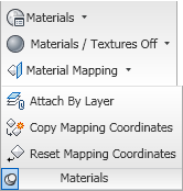 The Materials split button allows you to toggle the open/close state of the Materials palette (MATERIALS command) or to set the mapping of materials on selected object(s) (MATERIALMAP).
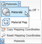 The command most recently selected from the drop-down will become the default for the button. The Materials/Textures drop-down list offers a choice of one of three states: both materials and textures off, materials on but textures off or both materials and textures on (VSMATERIALMODE).
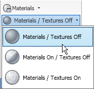 The button displays the current choice. The Material Mapping split button offers another way to use the MATERIALMAP command, this time with a preselected mapping type: Planar, Box, Cylindrical or Spherical.
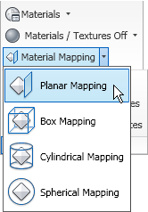 The main button appears to be fixed on "Planar". Selecting the Materials title bar will expand the panel to reveal three additional commands: Attach By Layer (assign materials by the object's layer - MATERIALATTACH), Copy Mapping Coordinates (copy material mapping from one object to another - MATERIALMAP, copY mapping to option) and Reset Mapping Coordinates (reset the mapping to the map defaults - MATERIALMAP, Reset mapping option).
Sun & Location Panel
The Sun & Location Panel contains commands related to including a sun-like light source in your renderings. The Sun Status command button allows you to toggle the sun on and off (SUNSTATUS system variable). The Sky button presents itself as a split button, but I was not able to find a way to make this button active. It will display the value of the SKYSTATUS systen variable, which allows you to set whether or not the sky illumination is computed at render time. Changing the value of SKYSTATUS changed the text shown with the button, displaying the current status. It may be that this only becomes active at an appropriate point in the rendering process, which is not something I do on a regular basis. The Set Location button allows you to specify the geographic location of the objects being rendered, so that the sun angles are set correctly. The Date and Time sliders become active when the sun is turned on, and allow you to specify the date and time of the rendering, and the sun angles will be set accordingly. The arrow icon at the far right side of the Sun & Location panel title bar toggles the Sun Properties palette, where you can make addtional sun parameter settings.
Lights Panel
The Lights Panel contains commands related to lighting.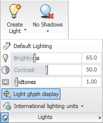 The Create Light split button allows you to place one of three types of lights: Point (POINTLIGHT), Spot (SPOTLIGHT) or Distant (DISTANTLIGHT).
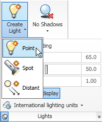 The last type chosen from the drop-down list becomes the command executed by the button; the "Create Light" text remains constant. The Shadows drop-down button allows you to set the type of shadows: none, ground or full (VSSHADOWS command).
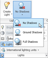 The last option chosen is displayed on the button. Select the Lights panel title bar to expand the panel. The first button on the expanded panel is the Default Lighting button (DEFAULTLIGHTING), which toggles between the default lighting and the lighting placed. The button is highlighted when Default Lighting is active. Three slider controls follow, giving control over Brightness, Contrast and Midtones (RENDEREXPOSURE). The Light glyph display button toggles the display of light glyphs in the drawing (LIGHTGLYPHDISPLAY). This button is also highlighted when active, in this case when the display of light glyphs is enabled. The lighting units drop-down allows you to choose from Generic, American and International lighting units.
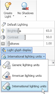 Generic lighting has no units and "standard" lighting. The other two use the units indicated and photometric lighting.
Camera Panel
The Camera Panel contains commands related to cameras.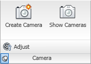 The Create Camera command button runs the CAMERA command, creating a camera object. The Show Cameras command button allows you to toggle the visibility of camera glyphs in the drawing file (CAMERADISPLAY). The button is highlighted when cameras are shown. Select the Camera panel title bar to expand the panel and reveal an additional button, Adjust, which allows you to change the view of a selected camera (AECCAMERAADJUST).
Animations Panel
The Animations Panel contains commands and controls related to animations.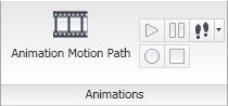 The Animation Motion Path command button allows you to set camera and/or target paths and make other animation settings in the Motion Path Animation dialog (ANIPATH command). There are four annimation control buttons: play, pause, record and save. The Walk/Fly split button gives you access to the Walk (3DWALK) and Fly (3DFLY) command buttons as well as the Walk and Fly Settings (WALKFLYSETTINGS).
 The last item selected becomes the command on the button.
The Render tab is the fourth static (always available) tab provided in the out-of-the-box ACA CUI. The image below and all screen captures in this article are based on the shipping version.

Tools Panel
The Tools Panel contains a single button that toggles the tool palettes on and off, setting the Visualization tool palette group current when toggling it back on.
 If you would prefer that it simply switch to the Visualization tool palette group, refer to this previous article for instructions on how to modify the CUIX file.
Render Panel
The Render Panel contains commands related to rendering.
 The Render split button split button allows you to render or render a region.
 The main button will change to run the most recently chosen option from the drop-down list. The Render Presets drop-down button offers a list of named, pre-established rendering settings. The most recently used choice is displayed when the drop-down list is collapsed.
 Choose Manage Render Presets at the bottom of the drop-down list to open the Render Presets Manager dialog, where you can edit the current settings, review the settings assigned to any of the standard presets as well as create or edit custom render presets (RENDERPRESETS command). The button below the Render Presets drop-down does not execute a command, but shows a histogram indicating the progress of a rendering in progress. Selecting the button at the left side of the third row on the main panel, Render Output File, toggles whether or not a rendered image is saved to a file. When enabled (bluish background, rather than gray), the Browse for File button at the right side of that same row (elipsis icon) becomes enabled, allowing you to specify the path and file name for the rendering file. The text box in the middle of the third row will display the path and name of the specified file. Select the Render panel title bar to expand the panel. A slider button shows the current render quality. The Render Output Size drop-down offers four standard image sizes; choose Specify Image Size at the bottom to open the Output Size dialog, where you can set a custom size for the rendered image.
 The Adjust Exposure button (RENDEREXPOSURE command) opens the Adjust Rendered Exposure dialog when the LIGHTINGUNITS system variable is not set to 0. The Environment button opens the Render Environment dialog, where you can enable or disable "Fog" and control various parameters thereof (RENDERENVIRONMENT). The Render Window button (RENDERWIN) opens the Render window without starting a rendering operation, allowing you to view previously rendered images for drawings with a "render history." The open arrow pointing to the lower right icon, at the far right side of the Render panel title bar, will toggle the Advanced Render Settings palette on and off.
Materials Panel
The Materials Panel contains commands related to render materials.
 The Materials split button allows you to toggle the open/close state of the Materials palette (MATERIALS command) or to set the mapping of materials on selected object(s) (MATERIALMAP).
 The command most recently selected from the drop-down will become the default for the button. The Materials/Textures drop-down list offers a choice of one of three states: both materials and textures off, materials on but textures off or both materials and textures on (VSMATERIALMODE).
 The button displays the current choice. The Material Mapping split button offers another way to use the MATERIALMAP command, this time with a preselected mapping type: Planar, Box, Cylindrical or Spherical.
 The main button appears to be fixed on "Planar". Selecting the Materials title bar will expand the panel to reveal three additional commands: Attach By Layer (assign materials by the object's layer - MATERIALATTACH), Copy Mapping Coordinates (copy material mapping from one object to another - MATERIALMAP, copY mapping to option) and Reset Mapping Coordinates (reset the mapping to the map defaults - MATERIALMAP, Reset mapping option).
Sun & Location Panel
The Sun & Location Panel contains commands related to including a sun-like light source in your renderings.
 The Sun Status command button allows you to toggle the sun on and off (SUNSTATUS system variable). The Sky button presents itself as a split button, but I was not able to find a way to make this button active. It will display the value of the SKYSTATUS systen variable, which allows you to set whether or not the sky illumination is computed at render time. Changing the value of SKYSTATUS changed the text shown with the button, displaying the current status. It may be that this only becomes active at an appropriate point in the rendering process, which is not something I do on a regular basis. The Set Location button allows you to specify the geographic location of the objects being rendered, so that the sun angles are set correctly. The Date and Time sliders become active when the sun is turned on, and allow you to specify the date and time of the rendering, and the sun angles will be set accordingly. The arrow icon at the far right side of the Sun & Location panel title bar toggles the Sun Properties palette, where you can make addtional sun parameter settings.
Lights Panel
The Lights Panel contains commands related to lighting.
 The Create Light split button allows you to place one of three types of lights: Point (POINTLIGHT), Spot (SPOTLIGHT) or Distant (DISTANTLIGHT).
 The last type chosen from the drop-down list becomes the command executed by the button; the "Create Light" text remains constant. The Shadows drop-down button allows you to set the type of shadows: none, ground or full (VSSHADOWS command).
 The last option chosen is displayed on the button. Select the Lights panel title bar to expand the panel. The first button on the expanded panel is the Default Lighting button (DEFAULTLIGHTING), which toggles between the default lighting and the lighting placed. The button is highlighted when Default Lighting is active. Three slider controls follow, giving control over Brightness, Contrast and Midtones (RENDEREXPOSURE). The Light glyph display button toggles the display of light glyphs in the drawing (LIGHTGLYPHDISPLAY). This button is also highlighted when active, in this case when the display of light glyphs is enabled. The lighting units drop-down allows you to choose from Generic, American and International lighting units.
 Generic lighting has no units and "standard" lighting. The other two use the units indicated and photometric lighting.
Camera Panel
The Camera Panel contains commands related to cameras.
 The Create Camera command button runs the CAMERA command, creating a camera object. The Show Cameras command button allows you to toggle the visibility of camera glyphs in the drawing file (CAMERADISPLAY). The button is highlighted when cameras are shown. Select the Camera panel title bar to expand the panel and reveal an additional button, Adjust, which allows you to change the view of a selected camera (AECCAMERAADJUST).
Animations Panel
The Animations Panel contains commands and controls related to animations.
 The Animation Motion Path command button allows you to set camera and/or target paths and make other animation settings in the Motion Path Animation dialog (ANIPATH command). There are four annimation control buttons: play, pause, record and save. The Walk/Fly split button gives you access to the Walk (3DWALK) and Fly (3DFLY) command buttons as well as the Walk and Fly Settings (WALKFLYSETTINGS).
 The last item selected becomes the command on the button.
Subscribe to:
Posts (Atom)