The muzzles have been removed, and participants in the Beta program for the 2008 release of AutoCAD Architecture (formerly known as Autodesk® Architectural Desktop) are now allowed to discuss the new features. I have been extraordinarily busy of late (was that not my excuse last year, too?), so bear with me while I try to find time to write about what you can expect in 2008.
One item that is really an AutoCAD feature but which I have not read about yet in any of the AutoCAD® 2008 blog postings (check out Lynn Allen's Blog and AutoCAD Insider by Heidi Hewett if you have not already done so) is yet another system variable to control the way linetypes display.
"Oh, dear! Not another variable to add to the existing CELTSCALE, LTSCALE and PSLTSCALE. I can not keep those straight - and now there is another?" you might be thinking. Before you don sack cloth and ashes and head out to wander aimlessly while cursing the fates aloud, relax - this is the feature you have wished for since paper space was introduced in Release 11.
The new system variable is called MSLTSCALE. A setting of 0 will result in the behavior you know and love so well in your current AutoCAD-based product. Setting it to 1 is where the magic begins. With MSLTSCALE set to 1, PSLTSCALE set to 1, LTSCALE set to whatever your office standard is for plotting at 1:1 (it may be 1, some use 0.5, my firm uses 0.375) and CELTSCALE set to 1 (not an absolute requirement, but I would recommend having the object linetype scale for newly created objects set to 1 and only change that in very rare instances when absolutely necessary on an object by object basis), you need NEVER CHANGE THESE VALUES AGAIN!
Yes, you read that correctly. Even if you are one of the elite who understand how LTSCALE and PSLTSCALE work in current releases, just think of all the time you will save trying to explain that to the unenlightened. One of the features of the new annotation scaling everyone is buzzing about is that now AutoCAD has a scale setting when the Model tab is active, and so now that you can tell AutoCAD the scale at which you are working, AutoCAD can figure out how to scale linetypes without you manually changing the value of LTSCALE. Perhaps this feature is not "worth the cost of the upgrade" - but it is a mighty fine addition and one that I hope to be using in the not too distant future.
February 23, 2007


February 16, 2007
Dealing With "*Xxx not found*" Location Property Result
Update for 2007 and later:
Change the formula properties in the examples below (or in the sample file downloaded from the Discussion Group) to test for "*Space not found*", rather than "*Area not found*". Area objects were merged into the new-and-improved Space object in 2007, so opening the sample file in 2007 or later will convert the Area objects in the sample file to Space objects, and the "not found" return value will change to "*Space not found*".
A location property will return *Xxx not found*, where Xxx is Space, Area or AEC Polygon, if the location grip for the object to which the location property is attached can not find an object of the type specified in the location property. This value is not a string - the VBScript TypeName and VarType functions crash when evaluating this value, so I have no idea what it actually is.
A denizen of the Autodesk Architectural Desktop Discussion Group posted a request for a method of dealing with this return value. The situation was one where a location property was being used with Areas, so that, where appropriate, a subordinate Area's area could be read into the main Area's properties and shown on a schedule. There would be main Areas, however, that would not have subordinate Areas; these would get the dreaded *Area not found* in the Location property and seing that in the schedule was not acceptable. When writing a Formula property to return "-" when there was no subordinate Area, the formula crashed when trying to compare the Location property value to *Area not found*. I have posted a sample file, done in ADT 2004, in a reply to that thread, that addresses the issued raised and also shows how you can create a Formula property from the Location that has a real number value with which calculations can be done. In the "not found" case, the real number is set to zero. Please note that the sample file was created to show possibilities, and the properties included are not optimized to a specific need. Some of the "formatted" properties would not be needed if the values were not being displayed in a Schedule Tag, as the "Unformmated" version could be placed as a column in a Schedule Table Style and a Property Data Format applied there. Some of the Formula properties might also be combined if there were no need for the intermediate results. Also note that the sample file was done in imperial units; the same concepts should apply to metric unit drawings as well. The image above shows the test objects in my sample file. There are three Area objects, two ten-foot square Areas, Living Room 100 and Bedroom 101, and a fifteen square foot Area for Balcony 101A. As you can see, Balcony 101A is subordinate to Living Room 100, as the Living Room Area's location grip is positioned over the Balcony Area. Neither the Balcony nor the Bedroom have a subordinate Area. For scheduling purposes, I created a Classification Definition that applies to Area objects, with two classifications - Main and Subordinate. The Living Room and Bedroom objects use an Area Style that has been classified as Main; the Balcony's Area Style is classified as Subordinate. This makes including only Main Areas in a Schedule Table easy, even if the Schedule Table is not in the same file as the Areas.
Writing an if condition to test the value of the Location property is fairly easy. Simply enclose the Location property and the test phrase in double quotation marks, and VBScript will do a text comparison. The problem is how to return the Location property value when an Area is found in a usable data format. You can not pass through the "raw" Location property value, as VBScript evaluates the entire formula, not just the logical path followed for each object, and *Area not found* will result in an error for Areas with no subordinate area. If the only need is a string which can be displayed in a Schedule Table, the solution is easy and the same as that for the if condition - enclose the property in double quotation marks. In the sample file, I have two location properties - SubordinateAreaFormatted and SubordinateAreaUnformatted. Both reference the BaseAreaUnformatted property of the subordinate Area; the formatted version uses the out-of-the-box Area Property Data Format; the unformatted version uses a custom Property Data Format called Standard-8, which is a copy of the Standard Property Data Format with the precision set to eight decimal places to maintain maximum precision, and, in this case, no zero suppression. The SubordinateAreaModified01 Formula property uses these two properties to test for "*Area not found*" and return "-" if found or the SubordinateAreaFormatted property as a string if an area is found. The formula is shown below:
This property can then be added to a Schedule Table, as shown below:
That is all well and fine if all you want to do is display the subordinate area in a Schedule Table. But what if you wanted to be able to have the Area as a numeric value, with which you could do some calculation? The same limitations encountered above will apply, and the solution used in the sample file is to accept that the Location property will have to be converted to a string to avoid an error in the formula, then to take that string and convert it into real number. In the sample file, this is handled by two separate Formula properties; you could easily combine them into one Formula property that does it all. The SubordinateAreaModified02 Formula property looks remarkably similar to the previous one, with the exception that the result when an Area is not found is "0.0" rather than "-" and the unformatted Location property is used. That is because we want to convert these values to real numbers, and non-numeric characters will cause an error.
The text values of the property would appear like the image below, if it were added to a Schedule Table.

The SubordinateAreaReal Formula property takes the value of the SubordinateAreaModified02 Formula property and uses the CDbl function to convert the strings to real numbers. Be aware that if you pass a string that contains any non numeric characters, other than an initial minus sign or a decimal point, using CDbl will result in an error. That is why the unformatted version of the Location value is used in the SubordinateAreaModified02 Formula property. The image below shows this property in a Schedule Table.
CDbl ( [SubordinateAreaModified02] )

A combined Formula property, not included in the sample file, might look something like this:
Now that we have a real number value, we can do math! [Trust me, that is a good thing.] Suppose that for rental purposes, the area of the balcony gets included at 75% of its actual area, along with the main area. The TotalAreaUnformatted Formula property is a simple, one-line calculation that does just that, and leaves the result unformatted should there be a need to do further mathematical operations on the result.
[BaseAreaUnformatted] + ( 0.75 * [SubordinateAreaReal] )
The TotalAreaFormatted Formula property simply passes through the value of the TotalAreaUnformatted property, applying the Area Property Data Format to it. If you are not going to include this value in a Schedule Tag, you could omit this property and use the TotalAreaUnformatted value as a column in your Schedule Table Style, changing the Property Data Format for the column to Area. The image below shows the formatted value in a Schedule Table.

You can click on the image below to see a larger version of the entire table, with some explanatory text below each column, or download the sample file from the Discussion Group thread and look at it live.

Change the formula properties in the examples below (or in the sample file downloaded from the Discussion Group) to test for "*Space not found*", rather than "*Area not found*". Area objects were merged into the new-and-improved Space object in 2007, so opening the sample file in 2007 or later will convert the Area objects in the sample file to Space objects, and the "not found" return value will change to "*Space not found*".
A location property will return *Xxx not found*, where Xxx is Space, Area or AEC Polygon, if the location grip for the object to which the location property is attached can not find an object of the type specified in the location property. This value is not a string - the VBScript TypeName and VarType functions crash when evaluating this value, so I have no idea what it actually is.
A denizen of the Autodesk Architectural Desktop Discussion Group posted a request for a method of dealing with this return value. The situation was one where a location property was being used with Areas, so that, where appropriate, a subordinate Area's area could be read into the main Area's properties and shown on a schedule. There would be main Areas, however, that would not have subordinate Areas; these would get the dreaded *Area not found* in the Location property and seing that in the schedule was not acceptable. When writing a Formula property to return "-" when there was no subordinate Area, the formula crashed when trying to compare the Location property value to *Area not found*. I have posted a sample file, done in ADT 2004, in a reply to that thread, that addresses the issued raised and also shows how you can create a Formula property from the Location that has a real number value with which calculations can be done. In the "not found" case, the real number is set to zero. Please note that the sample file was created to show possibilities, and the properties included are not optimized to a specific need. Some of the "formatted" properties would not be needed if the values were not being displayed in a Schedule Tag, as the "Unformmated" version could be placed as a column in a Schedule Table Style and a Property Data Format applied there. Some of the Formula properties might also be combined if there were no need for the intermediate results. Also note that the sample file was done in imperial units; the same concepts should apply to metric unit drawings as well.
 The image above shows the test objects in my sample file. There are three Area objects, two ten-foot square Areas, Living Room 100 and Bedroom 101, and a fifteen square foot Area for Balcony 101A. As you can see, Balcony 101A is subordinate to Living Room 100, as the Living Room Area's location grip is positioned over the Balcony Area. Neither the Balcony nor the Bedroom have a subordinate Area. For scheduling purposes, I created a Classification Definition that applies to Area objects, with two classifications - Main and Subordinate. The Living Room and Bedroom objects use an Area Style that has been classified as Main; the Balcony's Area Style is classified as Subordinate. This makes including only Main Areas in a Schedule Table easy, even if the Schedule Table is not in the same file as the Areas.
Writing an if condition to test the value of the Location property is fairly easy. Simply enclose the Location property and the test phrase in double quotation marks, and VBScript will do a text comparison. The problem is how to return the Location property value when an Area is found in a usable data format. You can not pass through the "raw" Location property value, as VBScript evaluates the entire formula, not just the logical path followed for each object, and *Area not found* will result in an error for Areas with no subordinate area. If the only need is a string which can be displayed in a Schedule Table, the solution is easy and the same as that for the if condition - enclose the property in double quotation marks. In the sample file, I have two location properties - SubordinateAreaFormatted and SubordinateAreaUnformatted. Both reference the BaseAreaUnformatted property of the subordinate Area; the formatted version uses the out-of-the-box Area Property Data Format; the unformatted version uses a custom Property Data Format called Standard-8, which is a copy of the Standard Property Data Format with the precision set to eight decimal places to maintain maximum precision, and, in this case, no zero suppression. The SubordinateAreaModified01 Formula property uses these two properties to test for "*Area not found*" and return "-" if found or the SubordinateAreaFormatted property as a string if an area is found. The formula is shown below:
If "[SubordinateAreaUnformatted]" = "*Area not found*" Then
 RESULT = "-"
Else
 RESULT = "[SubordinateAreaFormatted]"
End If
This property can then be added to a Schedule Table, as shown below:

That is all well and fine if all you want to do is display the subordinate area in a Schedule Table. But what if you wanted to be able to have the Area as a numeric value, with which you could do some calculation? The same limitations encountered above will apply, and the solution used in the sample file is to accept that the Location property will have to be converted to a string to avoid an error in the formula, then to take that string and convert it into real number. In the sample file, this is handled by two separate Formula properties; you could easily combine them into one Formula property that does it all. The SubordinateAreaModified02 Formula property looks remarkably similar to the previous one, with the exception that the result when an Area is not found is "0.0" rather than "-" and the unformatted Location property is used. That is because we want to convert these values to real numbers, and non-numeric characters will cause an error.
If "[SubordinateAreaUnformatted]" = "*Area not found*" Then
 RESULT = "0.0"
Else
 RESULT = "[SubordinateAreaUnformatted]"
End If
The text values of the property would appear like the image below, if it were added to a Schedule Table.

The SubordinateAreaReal Formula property takes the value of the SubordinateAreaModified02 Formula property and uses the CDbl function to convert the strings to real numbers. Be aware that if you pass a string that contains any non numeric characters, other than an initial minus sign or a decimal point, using CDbl will result in an error. That is why the unformatted version of the Location value is used in the SubordinateAreaModified02 Formula property. The image below shows this property in a Schedule Table.
CDbl ( [SubordinateAreaModified02] )

A combined Formula property, not included in the sample file, might look something like this:
If "[SubordinateAreaUnformatted]" = "*Area not found*" Then
 RESULT = 0.0
Else
 RESULT = CDbl( "[SubordinateAreaUnformatted]" )
End If
Now that we have a real number value, we can do math! [Trust me, that is a good thing.] Suppose that for rental purposes, the area of the balcony gets included at 75% of its actual area, along with the main area. The TotalAreaUnformatted Formula property is a simple, one-line calculation that does just that, and leaves the result unformatted should there be a need to do further mathematical operations on the result.
[BaseAreaUnformatted] + ( 0.75 * [SubordinateAreaReal] )
The TotalAreaFormatted Formula property simply passes through the value of the TotalAreaUnformatted property, applying the Area Property Data Format to it. If you are not going to include this value in a Schedule Tag, you could omit this property and use the TotalAreaUnformatted value as a column in your Schedule Table Style, changing the Property Data Format for the column to Area. The image below shows the formatted value in a Schedule Table.

You can click on the image below to see a larger version of the entire table, with some explanatory text below each column, or download the sample file from the Discussion Group thread and look at it live.

February 13, 2007
AutoCAD Architecture 2008
The 2007 release of Architectural Desktop will be the last - under that name. Those interested in an overview of the features in the newly christened AutoCAD Architecture 2008 may want to read this press release from Autodesk. You can also keep tabs on the 2008 rollout [and even sign up for e-mail notification or set up an RSS feed] at the Autodesk Preview 2008 site.
February 08, 2007
Creating a Wall Style with Actual Masonry Widths
The imperial masonry wall styles that ship with ADT use nominal dimensions for the masonry components; for example, an 8" CMU component is given a width of 8". Some may prefer to have the actual component widths used, 7 5/8" for the 8" CMU noted previously. A question came up in a thread in the Autodesk Architectural Desktop Customization Discussion Group from someone setting up such a wall style, having started from one of the out-of-the-box styles. After changing the widths of the masonry components, as well as reducing the Air Gap to 1", the wall endcap did not appear as desired. I posted a response and a sample file illustrating the need to create a new wall endcap style for the modified wall style, as ADT will scale the polyline graphics used to create the endcap for each component, to suit the actual width of the component. Since the two masonry components got 5/8" narrower, the scaled-down version of the original wall endcap resulted in the masonry component endcaps being "shorter" than those for the insulation, metal furring and GWB, whose widths remained the same. Here is how I created the new wall style, wall endcap style and wall opening endcap style in ADT 2004 for the modified wall. These same concepts can be applied any time you make a copy of an existing wall style and modify the widths of one or more components.
I used the out-of-the-box CMU-8 Rigid-1.5 Air-2 Brick-4 Furring wall style as my starting point, using the Style Manager to copy it from the out-of-the-box source file to a new file started with an ADT template file. I then copied and pasted that style in the new drawing file, renaming the style to CMU-7.625 Rigid-1.5 Air-1 Brick-3.625 Furring and editing the description of the wall style to match the planned changes. I also copied the associated CMU-8 Rigid-1.5 Air-2 Brick-4 Furring (End 1) wall endcap style and CMU-8 Rigid-1.5 Air-2 Brick-4 Furring (End 1)(2-Sided) wall opening endcap style to create the CMU-7.625 Rigid-1.5 Air-1 Brick-3.625 Furring (End 1) wall endcap style and the CMU-7.625 Rigid-1.5 Air-1 Brick-3.625 Furring (End 1)(2-Sided) wall opening endcap style, respectively. I edited the new wall opening endcap style to reference the new wall endcap style at the jamb start and jamb end. I then edited the CMU-7.625 Rigid-1.5 Air-1 Brick-3.625 Furring wall style and assigned the new wall endcap style and new wall opening endcap style on the Endcaps / Opening Endcaps tab as shown in the image below and edited the widths and offsets of the components on the Components tab, changing the widths of the Brick to 3 5/8", the Air Gap to 1" and the CMU to 7 5/8" and the offsets to coordinate, as shown in the image below. You can also see my preference for using engineering units rather than architectural units; I believe that the file I posted is set to architectural units.
 Note that even though new endcap/opening endcap styles were created and assigned, the actual endcap remains identical to the original, out-of-the-box version. I created the copies and assigned them up front in order to make it easy to generate the new endcap style using the Endcaps > Calculate Automatically option from the wall-object context [right click] menu. The default action there is to redefine the current wall endcap style, so by having a placeholder style with the desired name already in place, I need only to say "Yes" to the prompt and I am done.
The image below shows one end of a wall drawn with the original, out-of-the-box CMU-8 Rigid-1.5 Air-2 Brick-4 Furring wall style, with the polylines that define its wall endcap style positioned just above the end and a dimension string showing the widths of the various components. I generated the polylines using the as Pline option of the WallEndcap command. This typically inserts the polylines all "bunched up" and oriented for the right side of a horizontal wall; I rotated the polylines and lined them up relative to each one's respective component.

The next image shows what a wall using the new CMU-7.625 Rigid-1.5 Air-1 Brick-3.625 Furring wall style but with the out-of-the-box CMU-8 Rigid-1.5 Air-2 Brick-4 Furring (End 1) wall endcap style would look like. Notice that the ends of the Brick and CMU components are inset from the ends of the other components, due to the scaling of the defining polylines to match the reduced widths of those components. This is the condition that the new wall endcap style will need to address.
The final image shows the new wall style with the new wall endcap style. I copied the polylines from the original, out-of-the-box wall endcap style, then edited the polylines for the Brick and CMU components to reflect the modified component widths and moved them all to properly align with the wall components. I also copied and modified the dimension string, to show the changes in the example file and in the image below. Finally, I selected the wall, right clicked, and chose Endcaps > Calculate Automatically from the context menu. Following the prompts on the command line, I selected the polylines, chose not to erase them [as I wanted to keep them for the sample file - you may want to delete them if you are certain they are correct, or keep them and erase them later after you are certain the endcap is correct], said "Yes" to modify the current endcap style [but only do so if you have already assigned a new wall endcap style to the wall, as noted above - otherwise you would be changing the wall endcap style assigned to the original wall style, which would likely not be something you want to do] and asked that the "new" [modified] wall endcap style be applied as the wall style default. And that is it - except for editing the end of the example wall back to its original position, as I had the polylines in the position shown when I updated the wall endcap style, and ADT will extend the wall to align with the polylines when the WallAutoEndcap command ends. WallAutoEndcap, by the way, is the command that is executed by the Calculate Automatically menu choice; if you are allergic to the context menus or prefer to set up a tool palette tool, toolbar tool or a keyboard short cut to initiate the Calculate Automatically process, WallAutoEndcap is the command you will need to reference.
Download the sample file I posted in the Discussion Group thread if you want to see it live.
I used the out-of-the-box CMU-8 Rigid-1.5 Air-2 Brick-4 Furring wall style as my starting point, using the Style Manager to copy it from the out-of-the-box source file to a new file started with an ADT template file. I then copied and pasted that style in the new drawing file, renaming the style to CMU-7.625 Rigid-1.5 Air-1 Brick-3.625 Furring and editing the description of the wall style to match the planned changes. I also copied the associated CMU-8 Rigid-1.5 Air-2 Brick-4 Furring (End 1) wall endcap style and CMU-8 Rigid-1.5 Air-2 Brick-4 Furring (End 1)(2-Sided) wall opening endcap style to create the CMU-7.625 Rigid-1.5 Air-1 Brick-3.625 Furring (End 1) wall endcap style and the CMU-7.625 Rigid-1.5 Air-1 Brick-3.625 Furring (End 1)(2-Sided) wall opening endcap style, respectively. I edited the new wall opening endcap style to reference the new wall endcap style at the jamb start and jamb end. I then edited the CMU-7.625 Rigid-1.5 Air-1 Brick-3.625 Furring wall style and assigned the new wall endcap style and new wall opening endcap style on the Endcaps / Opening Endcaps tab as shown in the image below
 and edited the widths and offsets of the components on the Components tab, changing the widths of the Brick to 3 5/8", the Air Gap to 1" and the CMU to 7 5/8" and the offsets to coordinate, as shown in the image below. You can also see my preference for using engineering units rather than architectural units; I believe that the file I posted is set to architectural units.
 Note that even though new endcap/opening endcap styles were created and assigned, the actual endcap remains identical to the original, out-of-the-box version. I created the copies and assigned them up front in order to make it easy to generate the new endcap style using the Endcaps > Calculate Automatically option from the wall-object context [right click] menu. The default action there is to redefine the current wall endcap style, so by having a placeholder style with the desired name already in place, I need only to say "Yes" to the prompt and I am done.
The image below shows one end of a wall drawn with the original, out-of-the-box CMU-8 Rigid-1.5 Air-2 Brick-4 Furring wall style, with the polylines that define its wall endcap style positioned just above the end and a dimension string showing the widths of the various components. I generated the polylines using the as Pline option of the WallEndcap command. This typically inserts the polylines all "bunched up" and oriented for the right side of a horizontal wall; I rotated the polylines and lined them up relative to each one's respective component.

The next image shows what a wall using the new CMU-7.625 Rigid-1.5 Air-1 Brick-3.625 Furring wall style but with the out-of-the-box CMU-8 Rigid-1.5 Air-2 Brick-4 Furring (End 1) wall endcap style would look like. Notice that the ends of the Brick and CMU components are inset from the ends of the other components, due to the scaling of the defining polylines to match the reduced widths of those components. This is the condition that the new wall endcap style will need to address.

The final image shows the new wall style with the new wall endcap style. I copied the polylines from the original, out-of-the-box wall endcap style, then edited the polylines for the Brick and CMU components to reflect the modified component widths and moved them all to properly align with the wall components. I also copied and modified the dimension string, to show the changes in the example file and in the image below. Finally, I selected the wall, right clicked, and chose Endcaps > Calculate Automatically from the context menu. Following the prompts on the command line, I selected the polylines, chose not to erase them [as I wanted to keep them for the sample file - you may want to delete them if you are certain they are correct, or keep them and erase them later after you are certain the endcap is correct], said "Yes" to modify the current endcap style [but only do so if you have already assigned a new wall endcap style to the wall, as noted above - otherwise you would be changing the wall endcap style assigned to the original wall style, which would likely not be something you want to do] and asked that the "new" [modified] wall endcap style be applied as the wall style default. And that is it - except for editing the end of the example wall back to its original position, as I had the polylines in the position shown when I updated the wall endcap style, and ADT will extend the wall to align with the polylines when the WallAutoEndcap command ends. WallAutoEndcap, by the way, is the command that is executed by the Calculate Automatically menu choice; if you are allergic to the context menus or prefer to set up a tool palette tool, toolbar tool or a keyboard short cut to initiate the Calculate Automatically process, WallAutoEndcap is the command you will need to reference.

Download the sample file I posted in the Discussion Group thread if you want to see it live.
February 02, 2007
Steve Bennett On Multi-Site Deployment
Steve Bennett has started a series on deploying ADT at a firm with multiple sites in his 2D or not 2D blog. You may find the two articles currently posted of interest:
How to deal with 300 users that all want it their way - Part 1
How to deal with 300 users that all want it their way - Part 2
Be sure to check his blog later for the promised Part 3.
How to deal with 300 users that all want it their way - Part 1
How to deal with 300 users that all want it their way - Part 2
Be sure to check his blog later for the promised Part 3.
February 01, 2007
Free Software - Autodesk Design Review

In case you somehow managed to miss all of the other blog articles about this, Autodesk is now offering Design Review [formerly DWF Composer] as a free download. Get your copy here.
January 30, 2007
Save the Markers!!!

Thanks to Shaan Hurley for calling my attention to this dire cause. If you are like me, you spent many hours and countless dollars [yen, pounds, insert your local currency here] creating colored presentation drawings by applying felt-tip markers to your drawings while in school or on the job. Those were good times, and now that those fondly remembered markers are endangered, we owe our full support to them!
Be certain to sign the petition, or simply click here to see what all the fuss is about.
January 20, 2007
Scale-Dependent Schedule Tags in ADT 2006 or 2007
The introduction of Schedule Tag tools and the Define Schedule Tag wizard certainly were welcome and made creating single-scale tags ever so much easier. But since the tag tool was set up to always apply annotation scaling – my preferred method for single-scale tags – the scale-dependent tags do not work properly, as they want to be inserted at a scale factor of one.
One way to get a Tool palette tool to properly insert a scale-dependent tag would be to do it the old-fashioned way, by creating a custom-command type AEC Content file using the _AecAnnoScheduleTagAdd command. The old-fashioned infrastructure for doing so, including the ever-popular PropertySetDefs.dwg, is no longer there. And do you really want to have two source files for your Property Set Definitions? The new setup for ADT 2006 and 2007 has a single source file [Schedule Tables (Imperial).dwg, Schedule Tables (Metric).dwg or Schedule Tables Styles.dwg (Metric D A CH)] that holds the out-of-the-box Property Data Formats, Property Set Definitions, Schedule Table Styles and Multi-View Block Definitions, and that file is NOT in the AEC Content folder structure, when content is installed in the default folders.
In order for the _AecAnnoScheduleTagAdd command to work, you need to be able to specify a source file for the Property Set Definitions referenced by the Schedule Tag, and that file needs to be in the same folder as the tag or one folder above. The tag needs to be in the AEC Content folder structure. Unless you are starting a brand new deployment, moving the source file is not an option, as that would break all of the current tools that reference the current location.
There is a solution – use a Windows Shortcut somewhere in the AEC Content folder structure to “include” the folder of the source file, and then place your scale-dependent AEC Content files for your tags in one or more folders below that folder. Create a Tool palette tool by dragging the AEC Content file from the AEC Content tab of DesignCenter onto an editable tool palette.
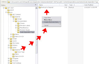 The image above shows the Room Tags folder that I created in the C:\Documents and Settings\All Users\Application Data\Autodesk\ADT 2007\enu\Styles\Imperial\, and illustrates the creation of a Windows Shortcut of the C:\Documents and Settings\All Users\Application Data\Autodesk\ADT 2007\enu\Styles\Imperial\ folder in the C:\Documents and Settings\All Users\Application Data\Autodesk\ADT 2007\enu\AEC Content\Imperial\Documentation\Scale-Dependent Tags folder that I added to the out-of-the-box default installation folders.
To create the AEC Content file, I started a new file “from scratch”. Creating AEC Content is just about the only time I will use that option, and the reason is to create the leanest possible content file. If there are unnecessary block definitions, dimensions styles, and other items in the AEC Content file, they will come along for the ride when inserting the tag. I used the Style Manager to copy the Aec7_Room_Tag_Project_Scale_Dependent Schedule Tag Multi-View Block from the C:\Documents and Settings\All Users\Application Data\Autodesk\ADT 2007\enu\Styles\Imperial\Schedule Tables (Imperial).dwg source file. I inserted an instance of the Aec7_Room_Tag_HiDtl_P view block used by that tag in model space of the file stared from scratch to serve as the icon graphics. Then I ran the PURGE command to get rid of the extra stuff that came along for the ride when copying the Multi-View Block. Finally, I fired up the AEC Content Wizard, which can be found on the Format pulldown, and filled out the three “pages” as shown in the images below. [Click on any image in this blog to see a larger version – excepting those images that were small enough to show full size.]
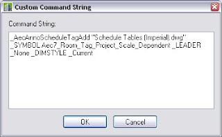
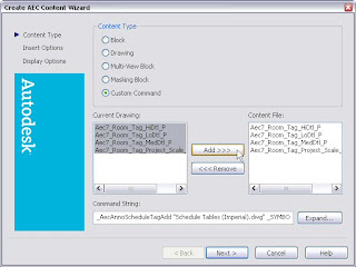 "Page 1": Adding the Multi-View Block and its view blocks to the Content File and specifying the Command String. See the image below for the full string. Be certain to specify the correct Property Set Definition source file name, and, if the name includes any spaces, to enclose the name in double quotation marks.
 "Page 2": You may prefer different settings, but be certain to specify "None" for additional scaling. Select the appropriate layer key.
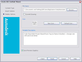 "Page 3": Specify the file location and name for the content file (see details in images below) and provide a detailed description. This description will appear in the bottom-right pane of the DesignCenter when the content file is selected, and will also become the default description for the Tool palette tool.
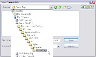
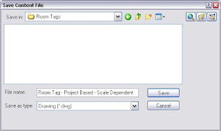 After all your settings are as you like, select the Finish button on the third "page" to create the AEC Content file. The new file shows up in Windows Explorer…
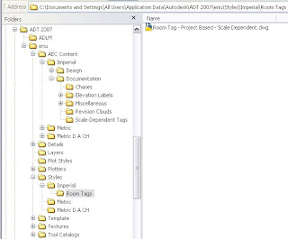 …as well as in the AEC Content tab of the DesignCenter. Note that the Scale-Dependent Tags folder I created under the Imperial Documentation folder now sports a "Shortcut to Imperial" folder within it [the Windows Shortcut], and that has a sub-folder called Room Tags, where I put my new AEC Content file. If you already had DesignCenter open to the Scale-Dependent Tags folder, you will need to collapse the Documentation folder by clicking on the "-" sign in front of it, then re-expand the Documentation folder by clicking on the "+" sign in from of it, to get the new content to show.
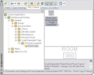 You could use the tag right from DesignCenter, but if you want to have your scale-dependent tag on your tool palette, you can now simply drag-and-drop the AEC Content file from the AEC Content tab in DesignCenter onto an editable tool palette.
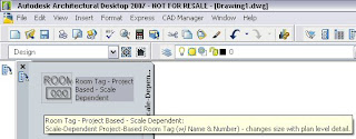 Using either the tool or the content file directly from DesignCenter, you can now place the scale-dependent tag with scale factors of one…
 …and get your tag to display properly when the Low Detail…
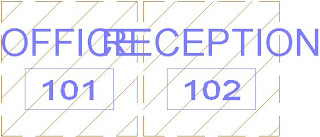 …Medium Detail…
 …and High Detail Display Configurations are set current.
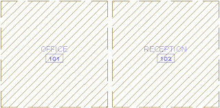 And it was all done without creating a second source file for Property Set Definitions or moving a source file and breaking any existing tools that reference it.
One way to get a Tool palette tool to properly insert a scale-dependent tag would be to do it the old-fashioned way, by creating a custom-command type AEC Content file using the _AecAnnoScheduleTagAdd command. The old-fashioned infrastructure for doing so, including the ever-popular PropertySetDefs.dwg, is no longer there. And do you really want to have two source files for your Property Set Definitions? The new setup for ADT 2006 and 2007 has a single source file [Schedule Tables (Imperial).dwg, Schedule Tables (Metric).dwg or Schedule Tables Styles.dwg (Metric D A CH)] that holds the out-of-the-box Property Data Formats, Property Set Definitions, Schedule Table Styles and Multi-View Block Definitions, and that file is NOT in the AEC Content folder structure, when content is installed in the default folders.
In order for the _AecAnnoScheduleTagAdd command to work, you need to be able to specify a source file for the Property Set Definitions referenced by the Schedule Tag, and that file needs to be in the same folder as the tag or one folder above. The tag needs to be in the AEC Content folder structure. Unless you are starting a brand new deployment, moving the source file is not an option, as that would break all of the current tools that reference the current location.
There is a solution – use a Windows Shortcut somewhere in the AEC Content folder structure to “include” the folder of the source file, and then place your scale-dependent AEC Content files for your tags in one or more folders below that folder. Create a Tool palette tool by dragging the AEC Content file from the AEC Content tab of DesignCenter onto an editable tool palette.
 The image above shows the Room Tags folder that I created in the C:\Documents and Settings\All Users\Application Data\Autodesk\ADT 2007\enu\Styles\Imperial\, and illustrates the creation of a Windows Shortcut of the C:\Documents and Settings\All Users\Application Data\Autodesk\ADT 2007\enu\Styles\Imperial\ folder in the C:\Documents and Settings\All Users\Application Data\Autodesk\ADT 2007\enu\AEC Content\Imperial\Documentation\Scale-Dependent Tags folder that I added to the out-of-the-box default installation folders.
To create the AEC Content file, I started a new file “from scratch”. Creating AEC Content is just about the only time I will use that option, and the reason is to create the leanest possible content file. If there are unnecessary block definitions, dimensions styles, and other items in the AEC Content file, they will come along for the ride when inserting the tag. I used the Style Manager to copy the Aec7_Room_Tag_Project_Scale_Dependent Schedule Tag Multi-View Block from the C:\Documents and Settings\All Users\Application Data\Autodesk\ADT 2007\enu\Styles\Imperial\Schedule Tables (Imperial).dwg source file. I inserted an instance of the Aec7_Room_Tag_HiDtl_P view block used by that tag in model space of the file stared from scratch to serve as the icon graphics. Then I ran the PURGE command to get rid of the extra stuff that came along for the ride when copying the Multi-View Block. Finally, I fired up the AEC Content Wizard, which can be found on the Format pulldown, and filled out the three “pages” as shown in the images below. [Click on any image in this blog to see a larger version – excepting those images that were small enough to show full size.]
 "Page 1": Adding the Multi-View Block and its view blocks to the Content File and specifying the Command String. See the image below for the full string. Be certain to specify the correct Property Set Definition source file name, and, if the name includes any spaces, to enclose the name in double quotation marks.
 "Page 2": You may prefer different settings, but be certain to specify "None" for additional scaling. Select the appropriate layer key.
 "Page 3": Specify the file location and name for the content file (see details in images below) and provide a detailed description. This description will appear in the bottom-right pane of the DesignCenter when the content file is selected, and will also become the default description for the Tool palette tool.
 After all your settings are as you like, select the Finish button on the third "page" to create the AEC Content file. The new file shows up in Windows Explorer…
 …as well as in the AEC Content tab of the DesignCenter. Note that the Scale-Dependent Tags folder I created under the Imperial Documentation folder now sports a "Shortcut to Imperial" folder within it [the Windows Shortcut], and that has a sub-folder called Room Tags, where I put my new AEC Content file. If you already had DesignCenter open to the Scale-Dependent Tags folder, you will need to collapse the Documentation folder by clicking on the "-" sign in front of it, then re-expand the Documentation folder by clicking on the "+" sign in from of it, to get the new content to show.
 You could use the tag right from DesignCenter, but if you want to have your scale-dependent tag on your tool palette, you can now simply drag-and-drop the AEC Content file from the AEC Content tab in DesignCenter onto an editable tool palette.
 Using either the tool or the content file directly from DesignCenter, you can now place the scale-dependent tag with scale factors of one…
 …and get your tag to display properly when the Low Detail…
 …Medium Detail…
 …and High Detail Display Configurations are set current.
 And it was all done without creating a second source file for Property Set Definitions or moving a source file and breaking any existing tools that reference it.
January 14, 2007
Hidden Feature Revealed: The Wall Style Components Browser
The other day I needed to create a new wall style, with double studs with an air space between. I started with an out-of-the-box style that had the right GWB and stud, and adjusted the offset of the "far side" GWB and copied the stud component. Then I remembered that I could copy the air space from another wall style using the Wall Style Components Browser. It occurred to me that I have not read much discussion about this feature, added with the 2004 release, and wondered if it had become "forgotten". If you have forgotten about this feature, or were never introduced to it, read on and add another tool to your Autodesk Architectural Desktop arsenal.
The Wall Style Components Browser allows you to easily add components to a wall style that match the way that component is set up in another style. That can help you maintain consistency across all of your wall styles. Ordinarily, when creating a new wall style, I would suggest starting with a copy of the existing wall style that is closest to what your new wall style needs to be, but for the purposes of illustration, I will create this one from scratch. The partition type I need is an interior metal stud partition that has good acoustic properties as well as a three-hour fire-resistance rating. The image below, taken from the USG Acoustical Assemblies catalog SA200, shows the partition we want to create
 By taking advantage of the Wall Style Component Browser, we were able to build a new wall style that matches the settings in existing wall styles with a few simple Copy and Pastes. How much easier could it be?
The Wall Style Components Browser allows you to easily add components to a wall style that match the way that component is set up in another style. That can help you maintain consistency across all of your wall styles. Ordinarily, when creating a new wall style, I would suggest starting with a copy of the existing wall style that is closest to what your new wall style needs to be, but for the purposes of illustration, I will create this one from scratch. The partition type I need is an interior metal stud partition that has good acoustic properties as well as a three-hour fire-resistance rating. The image below, taken from the USG Acoustical Assemblies catalog SA200, shows the partition we want to create

- Start a new drawing using an Autodesk Architectural Desktop template file. I am using the 2007 release for this exercise, and started with the out-of-the-box Aec model (imperial stb).dwt template. Open the Style Manager (one way, Format > Style Manager… from the pulldown menus). Expand the Architectural Objects folder under your new drawing in the left pane, right click on Wall Styles and choose New from the context menu.
- Give the new wall style a name, I chose Stud-1.625 GWB-0.500 3 Layers Each Side to match the out-of-the-box style-naming convention. In the right pane, select the General tab and add a description of 3 5/8" Stud Ptn. (Actual) with 3 Layers 1/2" Gypsum, again matching the format of the shipping content. If your office has a different convention, by all means follow that.
- Select the Components tab. You should have a default component, called "Unnamed". We will be deleting that later, but only after we add another component, as you always need to have at least one component. Click on the Wall Style Components Browser button [the tool tag reads "Wall Style Browser"], the bottom button of the four at the right side of the Components tab.
- The Wall Style Components Browser window opens.
- None of the wall styles in the 2007 version of that file have a half-inch thick GWB component or a 1 5/8" deep stud, but we can bring in a 5/8" thick GWB component and a 2 1/2" stud and modify them. I chose the Stud-2.5 GWB-0.625 2 Layers Each Side wall style. Clicking on this in the left pane displays the components in that wall style and their properties in the top right pane, and a preview of the wall style in the lower right pane.
- Select the Index 1 GWB component in the top right pane, right click and choose Copy from the context menu.
- Now we can delete the Unnamed component, by selecting it and clicking on the Remove Component button, second from the top at the left. Edit the GWB component, changing the Priority to 1220 (remember, we have three layers of GWB each side), the Width to 1/2" and the edge offset to 1". Select the edited component, right click, choose Copy from the context menu and finally right click and choose Paste from the context menu, twice, to add two more GWB components. Edit the Index 2 component, changing its Priority to 1210 and Edge Offset to 1/2". Edit the Index 3 component, changing the Priority to 1200 and Edge Offset to 0".
- Go back to the Wall Style Component Browser and copy the Stud component and paste it into the Components tab. Change the Width to 1 5/8" and the Edge Offset to -1 5/8".
- We are in the home stretch now. Select the Index 3 GWB component, right click, Copy, select the Index 4 Stud component, and then right click and Paste. Change the Edge Offset of the Index 5 GWB component to -2 1/8". Select the Index 2 GWB component, right click, Copy, select the Index 5 GWB component, right click and Paste. Change the Edge Offset of the Index 6 GWB component to -2 5/8". Select the Index 1 GWB component, right click, Copy, select the Index 6 GWB component, right click and Paste. Change the Edge Offset of the Index 7 GWB component to -3 1/8".


 There is not much to pick from at this point, since there are no other wall styles in our drawing. We could have used the Style Manager to copy some other styles into our file first, but if we do not need them, why clutter the file with them? Just as you can "open" a file in the Style Manager without actually opening the file, you can "open" a file in the Wall Style Component Browser and access the styles within. Click on the Open drawing icon at the upper left corner, then browse to the location of the file containing the wall style(s) from which you want to copy components. I chose the out-of-the-box Wall Styles – Stud (Imperial).dwg as the source file.
 Now click back in the Style Manager to make that the active window, right click in the right pane under the default component and select paste from the context menu.
 This will paste the component you copied in the Wall Style Component Browser into your wall style, with the same properties as it had in the source style. If you like, click on the Materials tab and note that the Material Definition assigned to the copied GWB component was also brought along into our style. Not too shabby for a single cut and paste.


 By taking advantage of the Wall Style Component Browser, we were able to build a new wall style that matches the settings in existing wall styles with a few simple Copy and Pastes. How much easier could it be?
January 10, 2007
List Definitions - Utility to Import/Export
Jimmy Bergmark of JTB World fame has made available a free utility program that will allow you to import and export List Definitions in ADT 2007 or ABS 2007. I have not yet had time to download this and try it out, but thought I would pass this along for those using the 2007 releases and List Definitions, as you may not want to wait until I find time to do so.
Subscribe to:
Posts (Atom)