Using a Tool to Change the Layer – Layer Key Override
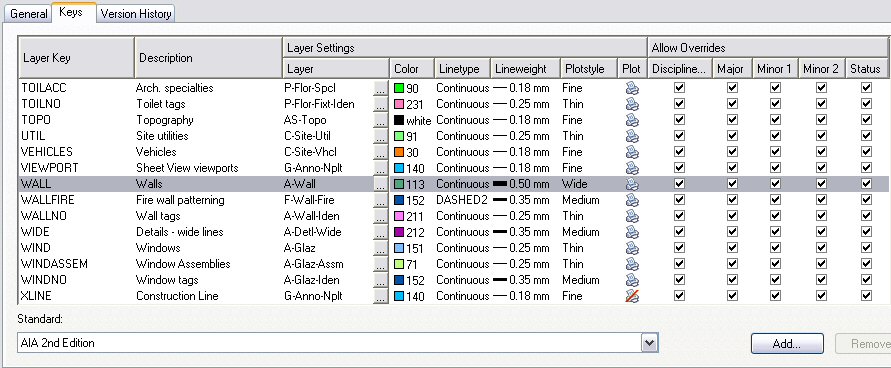
In order for this to work, you have to be using a Layer Key Style that permits overrides on the Descriptive Field you wish to override. You can check this by editing the Layer Key Style and looking at the Layer Key of interest on the Keys tab. The Allow Overrides columns are at the far right of the edit window. As shown below, there is a column for each Descriptive Field in the Layer Standard associated with the Layer Key Style; a checkmark in a column indicates that overrides are permitted. The AIA (256 Color) Layer Key Style shown permits overrides in all of the Descriptive Fields for the WALL key, so we can proceed.
For illustration purposes, lets assume you are using the AIA (256 Color) Layer Key Style and are perfectly happy with new walls being assigned to the A-Wall layer, but want your existing-to-remain walls assigned to A-Wall-E, and want that layer to have a different color, lineweight and plot style.
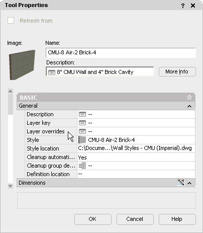
- You have checked the Layer Key Style and confirmed that it is set up to allow Layer Key Overrides to the Status Descriptive Field [see image above]. Now you need to set up a Tool palette tool that will create a wall but apply an override to the Status Descriptive Field so that it is placed on A-Wall-E. I i-dropped a tool for the out-of-the-box “CMU-8 Air-2 Brick-4” wall style onto a newly created [editable] tool palette from the out-of-the-box Design Tool Catalog – Imperial Tool Catalog. Create a wall tool using a style that you want to be able to draw on an alternate layer, right click on it and choose Properties… from the context menu.
- In the Tool Properties dialog, the first category is Basic, and the first subcategory in Basic is General. The third property in General is “Layer overrides”; this is the property we will be modifying.
- Click on the worksheet icon in the Layer overrides edit box to set the override[s] you want. The Select Layer Overrides worksheet will appear.
 If the “Do not specify Layer Overrides” toggle at the bottom of the worksheet is checked, left click on it to clear the check mark and unlock the edit box. You can now specify overrides for any of the Descriptive Fields on which your Layer Key Style permits overrides; in the example here, any of them. Our goal is to change the Status to “E” – you can either left click in the Override column, on the Status row, and type in “E” [without the quotation marks], or, if you know that the override you are applying has been entered as a predefined value for that Descriptive Field in the Layer Standard, select the ellipsis button [“…”] and the Choose a Prespecified Value dialog will appear, with a list of the values that have been prespecified for that Descriptive Field, including their descriptions. This may not seem such a big deal for our example, which only has one character and a fairly limited number of choices, but for the minor fields, with four characters and many more choices, it can be quite helpful. It is also good practice to assure that the layer you are creating conforms to your office’s Layer Standard, which should be set up with predefined values for all of the layers you use. If the list is too long for the dialog, you can use the scroll bars, or start typing the first character or two to home in on the value you want.
 - Select OK in the Choose a Prespecified Value dialog if you used it, and note that the override value now appears in the Select Layer Overrides worksheet. You can specify overrides for as many fields as you like; our example only requires overriding the Status Descriptive Field, so no additional settings need to be made.
- Select OK in the Select Layer Overrides worksheet to return to the Tool Properties dialog. Note that the Layer overrides edit box now contains a value, indicating the Layer Key Style to which the override applies followed by the override values, each separated by a comma. In our example, there are a number of commas in a row; the fact that there are no values between the commas indicates that those fields have no override. The “E” at the end indicates that the last Descriptive Field [Status] has an override of “E”. Select OK to close the Tool Properties dialog.
- Start a new drawing with the template file you would use for a new “model” or “construct” drawing, that is, a drawing in which you would draw an existing-to-remain wall. For this example, I used the out-of-the-box Aec model (imperial stb).dwt template file. Open the Layer Manager and see if the A-Wall-E is already defined. If it is, and it has your office standard settings for that layer, the layer is defined in your template file and your tool can be used with no further effort on your part. If not, you can use your tool, but be aware that while the name of the layer created will be overridden to A-Wall-E, the layer attributes assigned will be those specified for the WALL key in your Layer Key Style. In other words, they will match those of the layer it creates when no override is assigned, in this example, the A-Wall layer. That may still be all right, if you have an easy means of correcting the layer attributes for layers, such as layer scripts, an AutoCAD Standards file or an AutoLISP or VBA routine to reset your layers to the correct values. Use the tool to draw a wall or two, then select the wall and note that the name of the layer on which your wall was drawn is not that specificed by the WALL key, but has your overriden value.
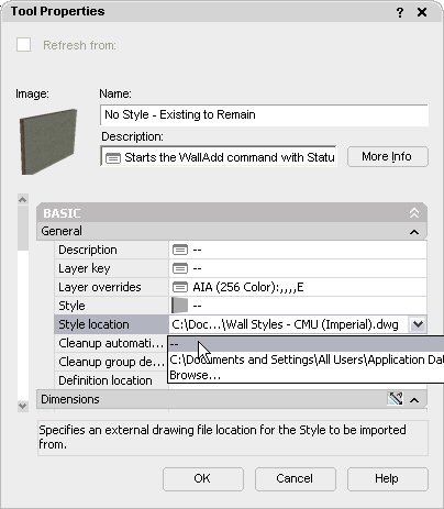
- One last item on the override method: If you expect to use many different wall styles for existing-to-remain walls and do not want to create multiple tools for each override condition you need, you can create a “generic” wall tool with the override attached but no style or style location specified.

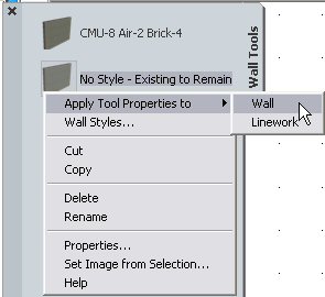
 You can use this tool to start the WallAdd command with the override, then select the desired style on the Properties palette, or draw one or more walls with the “normal” wall tool[s], then right-click on the “generic existing-to-remain” tool and choose Apply Tool Properties to > Wall from the context menu to move the wall[s] to the A-Wall-E layer.


The next and final installment will cover setting up and assigning a new layer key in a wall tool.
1 comment:
Good overview David. Thanks for posting these
Post a Comment