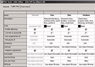

If your plot style is set to "Use object lineweight", then you need to look in the drawing for the lineweight that will be used. For "simple" AutoCAD objects, the object's lineweight will either be set directly on the object or, if the lineweight property is set to "ByLayer", the lineweight set to the object's layer will be used.

Open the Layer Manager to see what lineweight is assigned to a given layer.

For "complex" AutoCAD objects, such as block defintions, the lineweight used by a nested object can be assigned directly or be set to either "ByLayer" or "ByBlock". If it is set to "ByLayer", the lineweight assigned to the layer on which the object is created will be used, unless the object is on Layer 0, in which case the lineweight assigned to the layer of the parent object will be used. If it is set to "ByBlock", then the lineweight assigned to the parent object will be used [and that could be assigned directly, "ByLayer" or "ByBlock"].
The components of ADT objects behave the same way as nested objects in a block reference, but you need to look at the active display properties, on the Layer/Color/Linetype tab, rather than the Properties palette, to determine the lineweight assignment. Select an object, right click and choose Edit Object Display... from the context menu. Go to the Display Properties tab of the Object Display dialog, find the Display Representation[s] that are shown in bold, and click on the Edit Display Properties button to look at the display properties for the various components of that object.

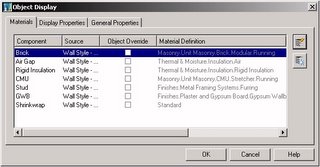
If you are using ADT 2004 or later, there is an additional "wrinkle" - certain components can be displayed by "By Material". If the linework in question is part of a component in ADT, when checking the display properties on the Layer/Color/Linetype tab, first look at the By Material column. If there is a check mark in the box in that column, then the display of that component is controlled by the display properties of the material assigned to the component, and not by the [grayed out] settings on the Layer/Color/Linetype tab for the object. Go to the Materials tab of the Object Display dialog to see what material is assigned to a given component. Select a component and then click on the Edit Material button to open the Material Definition Properties dialog for that material.

On the Display Properties tab, find the bold Display Representation and click on the Edit Display Properties button to look at the display properties for the various components of that material. You will need to know the component to which your linework belongs.

No comments:
Post a Comment