No, not computer cookies - the edible kind. That is why this is "off topic".
I took a couple of days off from work to be home while cable internet access was installed [finally!], shovel the results of an early-season snowstorm and engage in my annual Christmas cookie baking marathon. I wrapped that up first thing this morning and even got a little Christmas shopping done. I can not upload any of the cookies here, but I can tease you with a picture of the results.

- Gingerbread
- Sugar
- Peanut Butter
- Oatmeal Raisin
- Chocolate Chip
Shaan Hurley has announced in his Between the Lines blog that Autodesk is conducting a survey on blogs. If you are reading this, you have an interest in and, most likely, an opinion on blogs. Take the survey and have your voice heard.
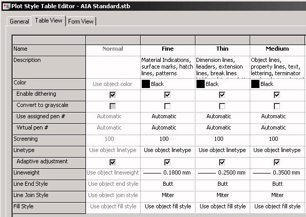
If you ever need to figure out why the lineweight of a particular piece of linework is plotting as it is, the following should help you determine where the lineweight is being set. The first place to look is at the plot style file used when the plot was created. The images here are taken from named plot style files [STB], but the same principals apply to color-dependent plot style files [CTB] - the only difference is in how the plot styles are assigned [by name or by color]. Take a look at the lineweight setting for each plot style. If it says "Use object lineweight", then you will need to search farther. If an explicit lineweight is assigned, then all objects/components that have that plot style assigned will use that explicit width, and any settings in the drawing file will be ignored.
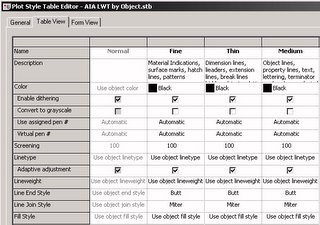
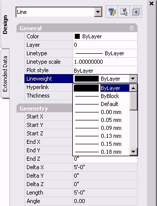
If your plot style is set to "Use object lineweight", then you need to look in the drawing for the lineweight that will be used. For "simple" AutoCAD objects, the object's lineweight will either be set directly on the object or, if the lineweight property is set to "ByLayer", the lineweight set to the object's layer will be used.
Open the Layer Manager to see what lineweight is assigned to a given layer.
For "complex" AutoCAD objects, such as block defintions, the lineweight used by a nested object can be assigned directly or be set to either "ByLayer" or "ByBlock". If it is set to "ByLayer", the lineweight assigned to the layer on which the object is created will be used, unless the object is on Layer 0, in which case the lineweight assigned to the layer of the parent object will be used. If it is set to "ByBlock", then the lineweight assigned to the parent object will be used [and that could be assigned directly, "ByLayer" or "ByBlock"].
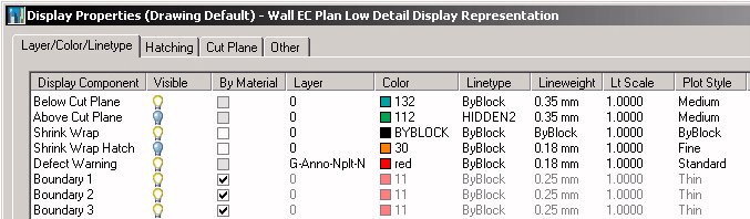
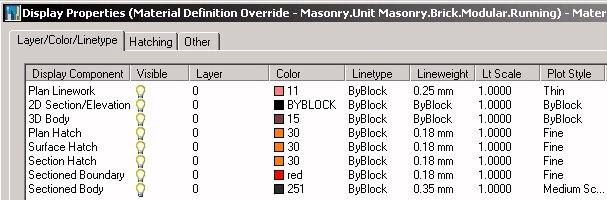
The components of ADT objects behave the same way as nested objects in a block reference, but you need to look at the active display properties, on the Layer/Color/Linetype tab, rather than the Properties palette, to determine the lineweight assignment. Select an object, right click and choose Edit Object Display... from the context menu. Go to the Display Properties tab of the Object Display dialog, find the Display Representation[s] that are shown in bold, and click on the Edit Display Properties button to look at the display properties for the various components of that object.
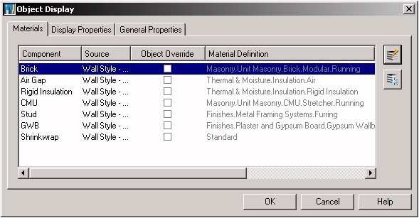
If you are using ADT 2004 or later, there is an additional "wrinkle" - certain components can be displayed by "By Material". If the linework in question is part of a component in ADT, when checking the display properties on the Layer/Color/Linetype tab, first look at the By Material column. If there is a check mark in the box in that column, then the display of that component is controlled by the display properties of the material assigned to the component, and not by the [grayed out] settings on the Layer/Color/Linetype tab for the object. Go to the Materials tab of the Object Display dialog to see what material is assigned to a given component. Select a component and then click on the Edit Material button to open the Material Definition Properties dialog for that material.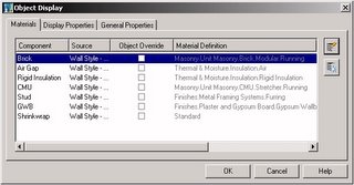
On the Display Properties tab, find the bold Display Representation and click on the Edit Display Properties button to look at the display properties for the various components of that material. You will need to know the component to which your linework belongs.
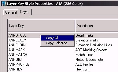
You can copy the contents of an Architectural Desktop Layer Key Style in a "tab delimited" format that can then be pasted into any spreadsheet program that accepts tab-delimited input, such as Excel, or into a word-processing program or even Notepad. All you need to do is edit the Layer Key Style, click on the Keys tab if it is not current, right click in the list box and choose Copy All from the context menu, as shown in the image below.
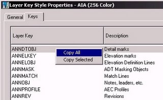
Edit a layer key style by opening the Style Manager [Format > Style Manager... from the pulldown menus], then expand the Multi-Purpose Objects category and the Layer Key Style item under the drawing file that has the Layer Key Style you wish to document. In ADT 2006, select the Layer Key Style in the left pane; in ADT 2005 or 2006, right click on the Layer Key Style in the left pane and choose Edit... from the context menu. You can also open the Style Manager, filtered for Layer Key Styles, by starting the Layer Manager [the ADT Layer Manager in 2004] and clicking on the Layer Key Styles icon in the upper left corner.
Pasting into spreadsheet program is ideal, because then you can take the information and sort the rows as you like. For example, if you want to know which Layer Keys use a given color, you can sort the rows by the column with the color number. You can also do this in ADT while editing a Layer Key Style by clicking on the header at the top of a column, but this does not always work as desired [sorting on the Plotstyle column in ADT 2004 does not work well - this may have been fixed in later releases].
If you have multiple versions of ADT installed on your computer, you may want to be careful about opening content browser library files [CBL extension] in a version of ADT other than the one in which it was created. Let me state that I do not know for certain that caused the problem I had earlier today - perhaps some other form of operator error is to blame.
I was in the middle of trying to figure out where project-based palette groups were stored and ran across the folder where the content browser library files are stored on my computer. The files for both 2005 and 2006 are in the same folder, but have different names. At some point, I had the 2006 library - ContentBrowserLibrary47.cbl - open [by what means, I do not recall, so I am not certain that I opened it with the AecCB47.exe application] and decided to open a different library. When I tried to reopen the 2006 library file, it was empty - not a single catalog - and the title had changed from "David Koch's Content Browser Library" to "contentbrowserlibrary47". After getting over the initial shock, and a few vain attempts at reopening the file in the hope that is would "magically" restore itself, I set about chasing down the location of all of the catalogs that were open in it. My custom catalog was easy, it was remembering what the out-of-the-box catalogs were and where they were located that was hard. I may not have even got all of them, but I think I got most of them. I did decide not to open "MyCatalog", as I found that if I keep my custom files in that catalog, and then install a newer version of ADT, it overwrites the "MyCatalog" file.
One thing I did discover is that if you navigate to a CBL file in Windows Navigator, right click and choose Open With, the Content Browser application is listed only as "AecCB EXE" - there is NO indication of what version of AecCB will be used. My suspicion is that I inadvertently opened my 2006 library with another version, and that may have lead to the file getting "cleared". So if you have multiple versions of ADT installed on your computer, I would advise being careful when changing libraries within Content Browser, and only open libraries that were created with the version of Content Browser that is currently open. I would avoid double clicking on a CBL file. If you do not want to open ADT first, then open the desired version of the Content Browser by double clicking on the EXE file or using the Start Menu, then opening the desired library file [if it is not the current default file].
I did make copies of the CBL files, adding "_backup" to the file name, in case I manage to make a similar mistake in the future. The usefulness of the backup will depend, of course, on whether I remember to make a new backup if I ever add or delete catalogs from the library in the future.
12/28/2005 Update:It would appear that the problems I was having can be ascribed to "operator error". It is still a good idea to regularly back up your CBL file.
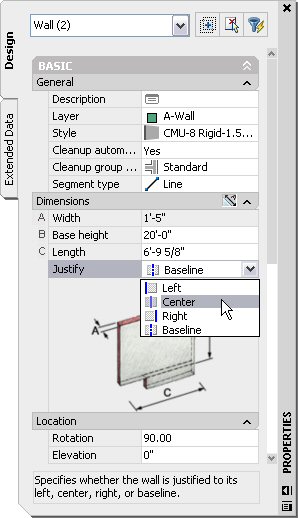
Using the Properties palette, you can change the justification of multiple walls at once. When doing so, the justification lines hold their positions and the walls shift to achieve the changed justification. If you are setting the graphline at the justification line, this makes some sense, as this will not affect wall cleanups.
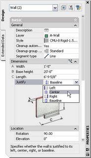
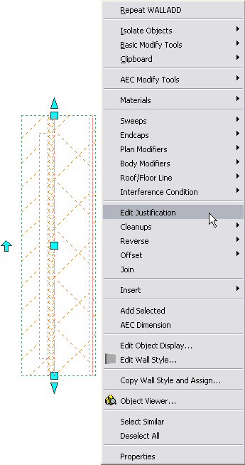
There are often occasions, however, when you have placed the walls correctly, but wish to change the justification – perhaps to make cleanup easier. Context menus to the rescue! The Edit Justification option on the right-click context menu for walls gives you the ability to change the justification while leaving the wall in its current position. The only caveat is that you must work on just one wall at a time. For any Command: line junkies out there [or Tool palette command tool aficionados], the command name is AecWallEditJustification, or somewhat more simply WallEditJustification.
- Select the wall, right click, and choose Edit Justification from the context menu, as shown below.
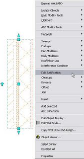
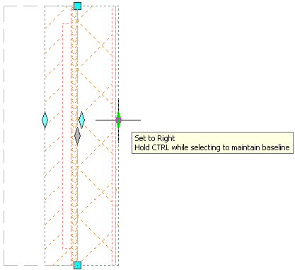
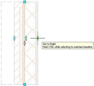
- You will see a series of diamond-shaped grips, as shown below. If you have not altered the out-of-the-box grip colors, the gray one represents the current justification location, and the cyan ones represent the other options. The left, center and right justifications are aligned across the wall center, and the baseline justification is slightly offset from the center. If you hover your mouse over a grip, you will get a dashed outline showing where the wall would move if you chose that grip along with a tool tip indicating the justification name. Note the second line of the tool tip: you can maintain the wall position by holding the CTRL key while selecting the grip to change the justification.
If you installed the ADT as AutoCAD shortcut and use it, you may have become familiar with the out-of-the-box AutoCAD Tool palette tools, and wish you had access to them when running ADT as ADT. If so, read on.
When I first tackled this problem, I discovered that I could run ADT as AutoCAD to get the AutoCAD Tool palettes on screen. Then I opened the Content Browser, which is a separate program and can be run independently of ADT. [The executable, AecCB47.exe, is located in the same folder as the acad.exe file, C:\Program Files\Autodesk Architectural Desktop 2006 in the default installation location.] I created a catalog, created palettes within it, and laboriously cut and pasted the tools from each palette. Afterwards, I got smarter and came up with the following:
- Start ADT as AutoCAD.
- Open the Options dialog, and go to the Files tab.
- If necessary, scroll down until you see the Tool Palettes File Locations category.
- Expand that category, and make note of the location where the AutoCAD tool palettes are stored.
- Close the Options dialog, and close ADT as AutoCAD.
- Start ADT as ADT.
- Open the Options dialog, go to the Files tab and expand the Tool Palettes File Locations category.
- Click on the Add… button.
- Click on the Browse… button and navigate to the folder where the AutoCAD tool palettes are stored. Leave this at the bottom of the list.
- Click on the OK button to exit the Options dialog, saving your changes.
- If necessary, change the current Palette Group to All Palettes, and you should be able to access the AutoCAD tool palettes.
At this point, if you wish, you can open the Content Browser, create a catalog, and drag-n-drop the AutoCAD tool palettes to the catalog. That is much easier than copying the tools on each palette to the clipboard and pasting them into a tool palette in the Content Browser, one palette at a time. Once you have the palettes it an ADT Tool catalog, you may, if you wish, go back into the Options dialog and delete the path to the AutoCAD tool palettes location, then i-drop them into your current workspace. That will set up a separate copy of the tool palettes, so if you plan to edit them, you may simply want to keep using them in the out-of-the-box location.
Note also that, when I did this using either method, the graphics for the tools when brought into ADT were not as crisp as they were in AutoCAD. You could always create new images and apply them in ADT if you really wanted to do so – I am not certain what impact that would have when running ADT as AutoCAD, so you may want to do that on a copy of the palettes.
New to ADT 2006 is the ability to export tool palette groups to an external file, with an extension of XPG. This file can then be copied to another machine and imported there. You could also export tool palette groups you no longer need, but want to save in case you need to restore them in the future.
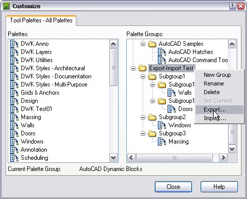
To export a tool palette group, right click on the spine of the Tool palettes and choose Customize... from the context menu. On the right side of the Customize dialog, in the Palette Groups list box, right click on a tool palette name and choose Export... from the context menu.
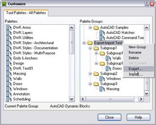
In the Export Group dialog, navigate to the folder in which you wish to store your XPG file, provide a name and select Save to create the file. The palette group you select, and any nested palette groups will be included in the exported file.
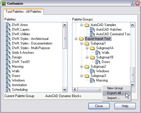
To export all of the palette groups, scroll down to the bottom of the Palette Groups list box and right click below the bottom line. Choose Export All... from the context list and save the file as noted above. All of the palette groups will be included in the exported file.
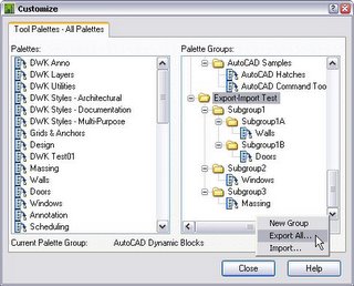
Importing palette groups is similar; right click a palette group or below the entire list and choose Import... from the context menu. Navigate to the desired XPG file and choose Open to import the palette group[s].
Note that this does not export or import the tool palettes associated with each group, so you can not share the actual palettes this way. I have found that if I import a palette group back onto the same computer where the palettes remain in the active profile, the palette groups are populated with the palettes, so it does "remember" which palettes were in each group. If you do this in a different profile, with a different tool palette workspace that does not have the same palettes, the groups will not be populated.
I do not have access to multiple computers that have ADT 2006 installed, so I do not know exactly how the groups are saving the list of palettes associated with each group, but I suspect it may be using the globally unique identifier [GUID] assigned to each palette. If the GUIDs of refreshable pallete pulled from the same, network-based catalog are the same, and those palettes are loaded on two different computers, you should be able to export the palette groups on one computer and import them on the other and have them be populated with the tool palettes. Unfortuately I can not test that suspicion to see if it holds true, or whether it is necessary to have the palettes installed before importing the palette groups.
Can it really be an entire year since I started this blog? The calendar says so, but it does not seem like it to me. Best of luck to all of you who are attending Autodesk University this year. I am not going this year, but hope to do so again in the future.
For those not going, but looking to improve their ADT skills, check out the AUGI Training Program course on Door/Window Assemblies offered this month by Steve Bennett.
ADT will report NA for an automatic property when that property does not have a value assigned for a particular object or style. The actual text displayed in controlled by the Property Data Format assigned to the property on the Formatting tab, in the General section, in the Not Applicable edit box. When reading a property that could have such an "empty" value into a formula property, VBScript will interpret the value as being "Empty", the formatting applied in the Property Data Format will not follow through. You can not test the value of the automatic property for "NA", or whatever string you assign to it. Update, 9/3/2006: If you enclose the text in the Not Applicable edit box in the Property Data Format with explicitly typed double quotation marks, the string value will be returned, rather than "Empty". See this article for additional information on this.
Attempting to perform mathematical operations, or even to convert the value to a particular type [using the CDbl function, for example] will result in an error and the formula will fail.
One solution for this, assuming the original automatic property has a numeric value when a value is assigned, would be to create an intermediate formula that uses either the VBScript TypeName or VarType function to test the automatic property value to see if it holds an empty value [TypeName returns the string "Empty"; VarType returns the integer 0]. If it does, have the RESULT of the formula be a number that is either meaningful to an "Empty" condition, or is at least unique - meaning that it would not be used when a numeric value is assigned. Then you can use the value of the intermediate formula in your final formula, testing, if necessary, for the value assigned for the "Empty" condition and taking the appropriate action.
A sample file demonstrating this condition and solution can be found in this thread in the Autodesk Architectural Desktop 2005 Discussion Group. The automatic property in question here is the door thickness. For cased opening door styles [using the Pass Through door type], there is no door, and the thickness property is "Empty" for doors using the Pass Through type. The request was to be able to have the thickness of existing doors show as "--" on the schedule while having the thickness show for new doors. The problem was the formula would fail when a new cased opening was scheduled, as applying the CDbl to the value of the automatic property in the formula property [to force whole numbers to be interpreted as reals] does not work when the value is empty.
The intermediate property in the example file, ThicknessForFormula, sets its value to 0 if the automatic property is "Emtpy", otherwise it passes through the value of the automatic property without doing anything to it. If there is no door leaf, then 0 would seem to be an appropriate value for the thickness. The final formula, ThicknessForSchedule, then tests that value and I chose to display "--" in the schedule if it is zero, otherwise the value is forced to be a double and the Length - Short Property Data Format is applied to get imperial architectural formatting.