March 29, 2009

AutoCAD® Architecture 2010 - UI Changes, Part 1 - The Application Menu

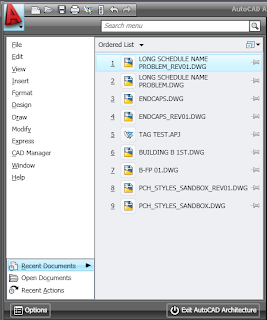
The Application Menu (accessed from the big red A in the upper left corner) has been revised, to coordinate with the overall user interface (UI) changes. The image below shows the 2009 Application Menu.(As always, select any reduced-size image to see the full-size version; use the back arrow in your browser to return here.)

The 2010 version drops the pull-down menu list, since those are not part of the new UI. (You can download CUIX and related files, along with instructions for restoring the pulldown menus and toolbars in this Autodesk Knowledge Base techinical solution, if you must. I would recommend giving the new UI a try before doing so. UPDATE: The referenced Knowledge Base Article has been removed from the Autodesk website. You can find a copy of the ZIP file that had been available in this thread in the AutoCAD Architecture Customization Discussion Group.) The Application Menu in 2010 provides one-stop shopping for commands that affect the file as a whole, as can be seen in the image below.
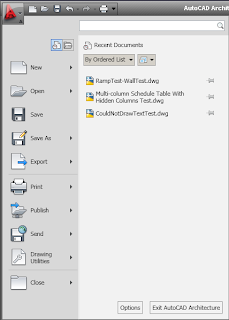
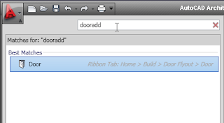
The search bar at the top of the right side of the Application Menu just might become your new best friend, at least until you become familiar with the Ribbon interface and learn where the commands you want are located.Selecting one of the items in the search list executes the referenced command, although it does not switch to the referenced Ribbon tab if that tab was not already current. This works great for finding commands in the "static" (always displayed) Ribbon tabs (Home, Insert, Annotate, Render, View and Manage, in the out-of-the-box ACD-A 2010 setup). Unfortunately, unless you already have one of the contexual tabs active, such as the Wall tab when a Wall object is selected, the search will not return "hits" for the commands available on the contextual tabs.

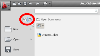
You can still access a list of recently opened documents or projects (see first 2010 image above; use the "pins" at the right of each item to keep it on the list) or a list of currently open documents (see image below), by choosing one of the icons at the top of the left column, circled in red below.The recent actions option available in 2009 appears to have been dropped.

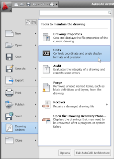
The "whole document" commands listed at the left side allow you to open, save, plot, publish and close drawings. Each item executes a command outright, and those with an arrow at the right have multiple related options that can be accessed selecting the arrow or simply hovering over the item. I will leave you to explore those options on your own, but will point out one that may be of particular interest, given that the Open Drawing Menu (accessed from the left pointing arrow in a circle icon on the far left side of the Drawing Window Status Bar since the 2004 release) has been deleted, just like the pulldown menus. I use that often to open the Drawing Setup dialog; the out-of-the-box Ribbon (as of the final Beta, anyway) does not have a way to directly execute the "Drawing Setup" command. You can use the Application Menu > Drawing Utilities > Units option to quickly open the Drawing Setup dialog (AecDwgUnitsSetup command)to the Units tab, and then, if necessary, switch to any of the other tabs to make the settings you need.Typing "aecdwgsetup" (opens to last active tab), "AecDwgUnitsSetup", "units" or, if you are using the out-of-the-box acad.pgp file or a custom variant thereof, "un" will also work. You can also open the Drawing Setup dialog directly to the Layering tab from the Ribbon at Home > Layers (flyout at the bottom of the panel) > Select Layer Standard, which runs the AecDwgLayerSetup command and opens the Drawing Setup dialog to the Layering tab. Direct access to the Scale and Display tabs appears to be limited to typed commands, AecDwgScaleSetup and AecDwgDisplaySetup, respectively.

March 15, 2009

More AutoCAD® Architecture 2010 Features


Spaces:

Draw order for Spaces is set automatically to "Back" so that any pre-existing objects or linework will be visible. This is a nice feature, especially if you are in a Display Configuration/View Direction that has a solid hatch turned on. One small problem is if you want to actually select an associative Space (or any Space that has Walls or other linework at the boundaries), as the graphics are "Back" and the solid hatch does not seem to provide a easy way to select the Space. You can switch to a Display Configuration, such as Low Detail, that does not display a solid hatch or remember that you can cycle through overlapping objects by pressing SHIFT + SPACEBAR.

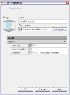
There is a new Space separator tool to make dividing Spaces that are not separated by Walls, using AutoCAD linework, easier. While you could do this manually before, the AecSpaceSeparator command makes this easier, and the tool allows you to assign a Layer Key to the separator linework. The out-of-the-box tool has the WALL layer key assigned, but you could just as easily make a copy of the tool and have the separator linework (a LWPOLYLINE object) placed on any layer for which you have a Layer Key, such as a non-plotting layer.


Structural Members:

There is a new automatic property source for Structural Members, "Length along Baseline", that projects the "net" member parts onto the baseline and then calculates the length. A "true" length can be determined from this property, which takes into account the effects of trim planes, offsets and interference conditions on the actual length of the Structural Member.

Project Navigator:

The PDF format has been added to the list of formats to which you can now print directly from within Project Navigator, which also includes the DWF and DWFx formats. I have not tried this myself, but the claim is made that the plotting utility has also been enhanced to allow creating PDFs with more accurate line weights.

AEC Dimensions:

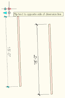
A new arrow-shaped grip allows you to flip the position of the dimension text to the opposite side of the dimension line, giving you more control over the placement of the text. This is most useful for nearly vertical dimension strings that are rotated beyond 90 degrees, so that you can put the text on the side you want. There is one grip per AEC Dimension object, and the grip affects all chains and all dimensions.


IFC Enhancements:

I have not had the need to work with IFC yet, so I will pass on the enhancements that are part of 2010 and leave it to those who use IFC to comment on these additions.

  • Space Boundary: Relevant information on the space boundary is attached for proper energy analysis in AutoCAD MEP.
  • Export and Import via the Command Line: You now have the option to turn off the dialog boxes and do IFC export and import operations from the Command Line.
  • Added IFC Physical Quantities: IfcQuantityCount, IfcQuantityLength, IfcQuantityTime, IfcQuantityVolume and IfcQuantityWeight.

Stairs:

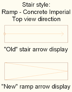
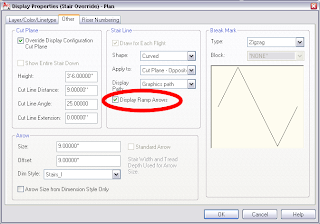
Done primarily for the German market, enhancements to Stairs include an "accurate graphic representation" of the stair cut meeting German standards, Stair and ramp tags supporting the German standard and a distinction between ramps and stairs. I was unaware that my Imperial Stairs had an inaccurate graphic representation. I did not install the German beta and I am not familiar with German market standards, so I can not offer much comment on these new features. I was not able to find any stair or ramp tags in either the Imperial or Metric content included with the English-language beta. Ramps in the beta I tested remained stair styles, with the treads and risers reduced to 0 width and stringers of various configurations pretending to be ramps and sometimes curbs. There is a new ramp arrow display toggle, that apparently shows ramps in accordance with the German standard; this is available, and the toggle is located on the Other tab of Display Representations intended for plan views. This will only display when the Display of both Tread and Riser are unchecked in the Flight Dimensions area on the Components tab of the Stair Style, so that may be the way AutoCAD Architecture distinguishes ramp Stairs from stair Stairs.

March 05, 2009

AutoCAD® Architecture 2010 - Editing Wall Cleanup In Place

Notice of the lifting of the NDA for the AutoCAD® Architecture 2010 Beta was finally received on Tuesday. The big change in 2010 is that the interface is going all Ribbon, all the time. The Visualization Workspace in 2009 made use of the Ribbon, but the others kept the previous pulldown menus and toolbars. In 2010, the entire interface has gone over to the Ribbon side. When selecting an AEC Object, a contextual Ribbon tab with commands related to the object will appear.

You can now also create multiple versions of the Quick Access toolbar as components of the CUI file, then assign one to each Workspace you define (rather than defining the Quick Access toolbar right in the Workspace, as was done in 2009). That would allow you to have the same Quick Access toolbar in multiple Workspaces and only need to edit it once to make changes to all.

If you are also a user of Inventor, or have friends or colleagues who are, you can now export Inventor part files and assemblies to AutoCAD Architecture as Multi-View Blocks.

Walls have been enhanced by adding fillet and chamfer to the list of commands available when editing wall endcaps in place. The one major, non-Ribbon feature added in this release is the ability to edit Wall cleanup in place, on a component-by-component basis, as shown in the following example.

Two stud Walls, with similar components, but different stud widths, where one face of stud aligns, will still not clean up automatically if there is no perpendicular Wall at the place where the two Walls meet.
In previous releases, one workaround for this was to simulate cleanup by creating open ended Wall Endcaps and offsetting one of them so that the linework was continuous, but the Wall graphlines did not meet.

In AutoCAD Architecture 2010, the new cleanup edit-in-place feature can be used to get the cleanup you want, without the need to create offset Wall Endcaps, and then fuss with the location of the graphline endpoints (and hope no one else messes with the results). This new feature is similar to the Wall Endcap edit-in-place feature that was greatly improved in the 2009 release.
  1. Select the Wall with the wider stud. Notice that the contextual Wall Ribbon tab appears and becomes active. In the Cleanup panel, select the Cleanup Edit in Place icon.The Wall Ribbon tab is replaced by the Edit in Place: Wall Cleanup contextual Ribbon tab. A number of commands related to editing cleanups in place can be found in this tab, but the edits needed for this task can be done using grip edit options.

  2. The first component of the Wall will initially be selected. While this component will need to be modified eventually, edit the stud component first, to avoid warning messages about having the GWB component, with its higher priority number, overlapping the stud component.The cyan circle grips represent vertices; the cyan rectangle grips allow you to operate on the edge on which it lies. As with other edit-in-place operations, you can use the Ctrl key to cycle through options once a grip has been selected. Notice that a vertex has been conveniently placed at the location where the adjacent Wall’s stud component ends, anticipating the edit to the stud component in the Wall being edited.

  3. Hover over the left edge grip and notice the options that the tool tip gives for editing that edge.Offset is the initial action, and is the one needed. Select the grip, and move the cursor "up" (away from the Wall end and the narrower Wall). Key in an offset value equal to the thickness of the GWB component, in this case 5/8". (I had polar tracking turned on, and 90 degrees was one of the angles. If you do not usually have polar or ortho turned on, you may want to check to be certain the offset distance is as desired, or explicitly key it in as @0,5/8). The editing of the stud component is now complete.
  4. Select the left GWB component. Hover over the right vertex grip and notice the options the tool tip gives for editing the vertex.Vertices have only two options, Move and Remove. Select the right vertex grip and move it “up” 5/8” by snapping to the endpoint of the offset stud component.
  5. Now select the edge grip. Press Ctrl twice to cycle to Add Vertex. Snap to the right endpoint of the offset stud edge.
  6. Select the edge grip on the angled edge. Press Ctrl twice to cycle to Add Vertex. Snap to the right endpoint of the narrower stud. The GWB component is now complete.
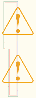
  7. Select the Finish icon in the Edits panel of the of the Edit in Place: Wall Cleanup tab to save the changes made. The GWB component on the side where the stud width changes now wraps the offset stud and cleans up with that of the narrower Wall.The cleanup alert triangles are now gone.

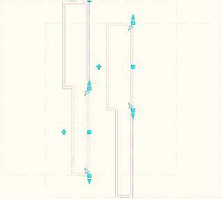
The dashed gray lines indicate that there is a cleanup override. These only show when the Graph Display Representation is active (when the Wall Justification Display is toggled on) and are on a non-plotting layer in the out-of-the-box display settings. There is also an additional cyan rectangular grip when the Graph Display Representation is active, which allows you to delete the cleanup override. NOTE: This grip will be coincidental with the end grip for the wall to which the overrides are attached, and therefore will not be selectable. Select the other wall, or select the dashed gray lines to choose the other wall and have access to the rectangular Remove Component Overrides grip. Do not use a crossing window on gray lines, as that will select both walls.

The image below has two pairs of walls, both with the offset on the wider stud as described above and the Wall Justification Display toggled on. In the pair to the left, the narrower stud wall is selected, and the rectangular Remove Component Overrides grip can be seen at the top end of the wider stud wall. In the pair to the right, the wider stud wall is selected, and the rectangular Remove Component Overrides grip is hidden by the Wall End grip. (You can tell there are at least two active grips there because no tool tip displays when hovering over the Wall End grip.)
The screen captures above were made with an earlier version of the Beta. The Ribbon icon for the Add Selected command on the Wall ribbon, partial visible in the screen capture above, has been changed in the final Beta. Since this is not the focus of this article, I did not see the need to create a new screen capture. I walked through the above steps in the final Beta and did not notice any other variation from the images shown. As always, you can click on any reduced image to see the full-size version; use the Back function of your browser to return to the main article.