The Annotate tab is the third static (always available) tab provided in the out-of-the-box ACA.cuix. The image below and all screen captures in this article are based on the shipping version.

Tools Panel
The Tools Panel contains a single button that toggles the tool palettes on and off, setting the Document tool palette group current when toggling it back on.
 If you would prefer that it simply switch to the Document tool palette group, refer to this previous article for instructions on how to modify the CUIX file.
Text Panel
The Text Panel contains commands related to the creation and editing of text.
 The Text command button starts the MTEXT command. The Check Spelling command button allows you to run the SPELL command to check the spelling of words in the drawing. The Text Style drop-down button displays the name of the current text style and allows you to set any other text style defined in the drawing current.
 Select Manage Text Styles... at the bottom of the drop-down to open the Text Style dialog if you need to create a new text style. The Find text button offers an edit box on the left where you can enter the text string for which you want to search/replace and a button on the right that opens the Find and Replace dialog. The previously used Find string will be displayed in the text box after searching or replacing is complete. The final button on the main panel is the Annotation Text Height drop-down, which displays the current default text height, as stored in the TEXTSIZE variable. When you first start up ACA, there is only one value in the list. As you use the TEXTSIZE variable to change the default text height or as you open/start additional drawings that have a different default text height set, the additional values will appear on the list. Note that changing the height of existing MTEXT (on the MTEXT editor bar or on the Properties palette) does not add items to the list.
Selecting the Text title bar will expand the panel to reveal four additional commands. The Scale button runs the SCALETEXT command, which allows you to rescale selected text objects without changing their individual locations. The Justify button changes the justification point of text, using the JUSTIFYTEXT command. The Field button runs the FIELD command. The Update Fields button allows you to manually update field values with the UPDATEFIELD command.
Dimensions Panel
The Dimensions Panel contains commands related to dimensioning (AEC and AutoCAD).
 The AEC Dimension split button allows you to choose one of three AEC Dimension ribbon tools, each offering a different AEC Dimension style (AEC Dimension Interior, AEC Dimension Exterior and AEC Dimension Exterior R.O.).
 Note that for this split button, the command that the top half of the button will run directly will change to the last item chosen on the drop-down list. If you have custom AEC Dimension styles for which you have (or can make) tool palette tools, you could customize the ACA.cuix file and add your styles to the list. The top row of the main Dimensions panels features a series of buttons that allow various types of AutoCAD Dimensions to be placed. These should be familiar to anyone who used the old Dimension toolbar in previous releases. Starting from the left, you have the Dimension, Linear button (DIMLINEAR command); a split button with the Continue (DIMCONTINUE, always available on the left part) and Baseline (DIMBASELINE) on the drop-down;
 the Dimension, Aligned button (DIMALIGNED); the Dimension, Angular button (DIMANGULAR); a split button with Radius (DIMRADIUS) and Diameter (DIMDIAMETER) on the drop-down (Radius is initially featured on the left part, but this split button will change to the last one used);
 and, at the right end, the Dimension, Center Mark button (DIMCENTER). The second row on the main panel has a single button, AEC Dimension Style, that will open the Style Manager, filtered for AEC Dimension Styles (AECDIMSTYLE). At the left of the third row is the Dimension Style button (DIMSTYLE), which opens the Dimension Style Manager dialog for creating and editing AutoCAD Dimension Styles. The balance of the third row features the Dimension Style drop-down button, which displays the name of the current AutoCAD Dimension Style, and allows you to set a different one current by selecting it from the drop-down list. Selecting the Dimensions panel title bar will expand the panel and reveal four additional dimension-related commands: Dimension Spacing (DIMSPACE), Ordinate (DIMORDINATE), Tolerance (TOLERANCE) and Arc Length (DIMARC).
Scheduling Panel
The Scheduling Panel contains commands related to the ACA Schedule feature.
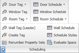 All of the commands in this panel that add a specific Tag or Schedule Table are ribbon tools. At the top of the first column, the Door Tag drop-down button allows you to use either of the out-of-the-box Door Tags, non-project-based or project-based.
 The Window Tag button adds the out-of-the-box Window tag. The Room Tag drop-down button offers a choice of three tags for Spaces: the non-project-based Room Tag, the Room Tag - Project Based and the Room Tag - BOMA.
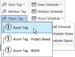 The second column features tools that allow you to add a Schedule Table to your drawing. The Door Schedule drop-down button offers the non-project-based and project-based Door Schedules
  The Window Schedule button allows you to add a Window Schedule, and, with the Room Schedule drop-down button, you can add the out-of-the-box Room Schedule, Space Schedule - BOMA or Space Inventory Schedule.
 Selecting the Scheduling title panel expands the panel, revealing tools to add Wall Tags and Schedules, as well as the Create Tag (DEFINETAG - opens the Define Schedule Tag "wizard" dialog), Renumber Property Sets (PROPERTYRENUMBERDATA - opens the Data Renumber dialog) and Schedule Styles (SCHEDULESTYLE - opens Style Manager, filtered for Schedule Table Styles). The Evaluate Space tool runs the AECSPACEEVALUATION command, which opens the Space Evaluation dialog.
Callouts Panel
The Callouts Panel contains commands related to adding callouts.
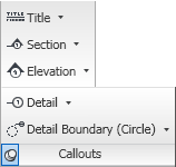 All of the buttons on this panel are split buttons and all of the tools therein are ribbon tools, allowing you to add out-of-the-box callouts without using the Properties palette directly. See the image below for the various callouts available for each type.
The most recently used command in each drop-down list becomes the featured command on the button.
Keynoting Panel
The Keynoting Panel contains commands related to adding keynotes and "other notes".
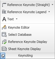 The three buttons on the main panel are all split buttons and all of the tools therein are ribbon tools, allowing you to add keynotes, keynote legends and text/leadered text/leadered symbols (the "other notes") without using the Properties palette directly. The options are shown in the image below; the most recently used command on each drop-down will become the featured command on the button.
 Commands on the expanded panel (select the Keynoting title bar) allow you to open up the Keynote Editor (LAUNCHKEYNOTEEDITOR command), select a database to be added to the list of available keynote databases (Select Database - KEYNOTEDATABASERESELECT) and toggle the display of either Reference or Sheet keynotes (Reference Keynote Display - REFERENCEKEYNOTETOGGLE / Sheet Keynote Display - SHEETKEYNOTETOGGLE).
Markup Panel
The Markup Panel contains commands related to drawing revisions.
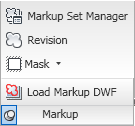 The Markup Set Manager command button (MARKUP command) opens the Markup Set Manager palette, allowing you to manage the DWF markups in the drawing. Draw layer-keyed revision clouds with the Revision command button (ANNOREVISIONCLOUDADD). The Mask split button allows you to add Mask Blocks or Wipeouts.
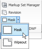 The button portion always displays the Mask command. One additional command is available on the expanded panel (select the Markup title bar), Load Markup DWF (OPENDWFMARKUP), which allows you to load a DWF file which contains markups into your drawing.
Annotation Scaling Panel
The Annotation Scaling Panel contains commands related to annotation scaling.
 The Currnent Scale split button allows you to add or delete the current scale from selected annotative objects. The most recently selected option becomes the button command.
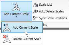 The Scale List command button (SCALELISTEDIT command) opens the Edit Scale List dialog, which allows you to add to, edit, delete from and rearrange the order of the listed pre-defined drawing scales. The Add/Delete Scales command button allows you to add or remove drawing scales from selected annotative objects (OBJECTSCALE). You can align all scale representations of an annotative object (should any individual representations have been grip edited) with the current scale representation (not the original "insertion" point) by using the Sync Scale Positions command button (ANNORESET).
2 comments:
Hi, how can I add the callouts and keynoting panels to my acad?
Karen:
Do you have AutoCAD Architecture, or just vanilla AutoCAD? If you have AutoCAD Architecture, then the ACA.cuix file should have those panels included, already. If you only have plain AutoCAD, then you will not be able to add those panels, as the commands/features they run/use are not available in plain AutoCAD.
Post a Comment