Back when AutoCAD® Architecture 2008 was shiny and new, I wrote an article about how to create a desktop shortcut to run AutoCAD Architecture as AutoCAD®, if you did not specify that such a shortcut be created at the time of installation (or deployment creation). Those instructions are still good, but I had the occasion to make a Screencast illustrating the process for AutoCAD Architecture 2015, and I thought I would share that here. In the Screencast, I chose to set the profile name in the shortcut to one that did not previously exist.
April 10, 2017


April 02, 2017
AutoLISP: Creating a Zero-padded String
In one of the Autodesk Forums, someone had asked for a routine that would put each Polyline in a drawing file on a separate layer. That sounded like a fun challenge, and in the process of putting together a bare-bones solution, I had to decide how these new layers would be named. (I chose to let all of the other layer properties remain at their defaults.). Since I was using a while loop that included an integer-based counter variable to process each Polyline in turn, it seemed simple enough to use that integer value as part of layer name, to make the name unique for each Polyline. Being somewhat retentive, I wanted all the layer names for a given run of the routine to have the same number of characters in them, but there was no way to know up front how many Polylines there would be in any given file.
Once in a file, it is easy enough to determine the total number of polylines, and then to use the itoa AutoLISP function to convert that integer to a string and the strlen function to determine how many characters that largest number would have. To get all of the numeric strings to that same length, I wanted to use "zero padding"; that is, I wanted to add "0" characters to the front of shorter numeric strings to bring the total string length up to that of the largest number. The subroutine I wrote to do this turned out to be elegantly simple (or so I thought), so I decided to post the code here.
Somewhat less complicated than the Integer To String - Zero Padding node I created for Dynamo, but the same net result.
Once in a file, it is easy enough to determine the total number of polylines, and then to use the itoa AutoLISP function to convert that integer to a string and the strlen function to determine how many characters that largest number would have. To get all of the numeric strings to that same length, I wanted to use "zero padding"; that is, I wanted to add "0" characters to the front of shorter numeric strings to bring the total string length up to that of the largest number. The subroutine I wrote to do this turned out to be elegantly simple (or so I thought), so I decided to post the code here.
(defun ZEROPAD ( ;_ Arguments:
  inum   ; Number to be converted to zero-padded string [integer].
  ichar   ; Number of characters in zero-padded string [integer].
  / ;_ Local variables:
  ilen   ; Number of characters in integer to be converted [integer].
  snum   ; Integer to be converted as a string [string].
        ) ;_ End arguments and local variables.
  (setq snum (itoa inum)  ; String equivalent of integer to be converted.
 ilen (strlen snum)  ; Length of integer string.
  ) ;_ End setq.
  (while (< ilen ichar)   ; While integer string length is less than target length...
    (setq snum (strcat "0" snum) ; ...add "0" to front of string and...
   ilen (1+ ilen)  ; ...increment string length.
    ) ;_ End setq.
  ) ;_ End while.
  snum     ; Return final string.
) ;_ End ZEROPAD.
Somewhat less complicated than the Integer To String - Zero Padding node I created for Dynamo, but the same net result.
March 31, 2017
ACA: Nested XLINEs Unselectable
If you include an XLINE in a Block Definition, when you place an instance of that Block, you will not be able to select the XLINE. This brief Screencast starts out with two XLINEs, a CIRCLE and a square closed POLYLINE. As you can see, the XLINEs can be selected when they are placed directly in the drawing. But after putting all four elements into a Block Definition, you cannot select the resulting BLOCK REFERENCE by left clicking on the nested XLINE or by running a crossing window over the XLINE.
Putting an XLINE in a Block Definition is not something I have ever needed to do, but if you have a use case for it, be aware of this limitation. NOTE: If the Block Definition contains only XLINEs, then you can select the BLOCK REFERENCE by selecting one or more of the nested XLINES. They only become unselectable when there are other object types included in the Block Definition.
Putting an XLINE in a Block Definition is not something I have ever needed to do, but if you have a use case for it, be aware of this limitation. NOTE: If the Block Definition contains only XLINEs, then you can select the BLOCK REFERENCE by selecting one or more of the nested XLINES. They only become unselectable when there are other object types included in the Block Definition.
February 23, 2017
Autodesk Answer Day - March 8, 2017
The next Autodesk Answer Day will be held on March 8, 2017, and will focus on AEC Products. The English-language event will run from 6:00 am to 6:00 pm US Pacific Time and cover BIM 360, Civil 3D, InfraWorks 360 and Revit. The German-language event will run from 10:00 am to 5:00 pm Central Europe Time and cover AutoCAD Produktfamilie - Deutsch (AutoCAD and Civil 3D) and Revit - Deutsch.
You can find more details in this AutodeskHelp blog article.

You can find more details in this AutodeskHelp blog article.
February 17, 2017
ACA: Wall Cleanup Tip
Here is an additional Wall Cleanup tip, for a condition that comes up just infrequently enough that I forget to check for this up front. If you have a "base" drawing file (Construct or Element for those of you using Project Navigator and the Drawing Management system) in which the Walls all clean up just fine and also have a "host" drawing file into which that base drawing is externally referenced, in which all (or nearly all) of the Walls from that external reference are showing cleanup errors, the first thing to check is whether or not you have two or more instances of the external reference, all on top of each other. If the Wall Cleanup Group(s) assigned to the Walls in the base drawing allow for cleanup between host and xref drawings (check the Design Rules tab of the Wall Cleanup Group Definition), then the Walls will all be trying to cleanup with the "same" Wall in the other instance(s), generating the cleanup errors. Remove all but one instance of the externally referenced file to eliminate the duplicates and you will likely see your cleanup problems go away.


February 15, 2017
Revit: Cannot Tag Room in a Linked Revit Model
I ran into a case of this today, and as I checked a number of other things that were not the cause of the problem before I found this Autodesk® Knowledge Network article, I thought I would document it here so I can find it faster in the future.
The problem was that the linked model did not have any Rooms in the equivalent phase that was set in the host file Views in which the Room Tags were to be placed. Since Rooms are phase-specific, they need to be recreated for each phase.
In this particular case, there were variations in the names that were given to the phases. To verify how the phases for a particular linked file are mapped (and make any necessary adjustments):
The problem was that the linked model did not have any Rooms in the equivalent phase that was set in the host file Views in which the Room Tags were to be placed. Since Rooms are phase-specific, they need to be recreated for each phase.
In this particular case, there were variations in the names that were given to the phases. To verify how the phases for a particular linked file are mapped (and make any necessary adjustments):
- In the host file, select the linked model.
- On the Properties palette, select the Edit Type button.

- In the Type Properties dialog, under the Other category, select the Edit button to the right of the Phase Mapping parameter.

- In the Phases dialog, you can assign the appropriate phase from the linked file to each phase in the host file. Revit will usually match up phases with the same name. (I am not sure what happens if the same names are used, but the phases are in a different order. That is such bad practice that I do not even want to test it.) Selecting in the Phase from linked file column next to a given host Phase will activate a drop-down list, which can be used to select from the phases defined in the linked file.


January 28, 2017
Seek-ing Content?
If you made use of the Autodesk® Seek, you should know that as of January 16*, 2017, that service has been transferred to BIMobject® Cloud Solution. Links to Autodesk Seek will be redirected to BIMObject. Read more about the transfer in this Autodesk Knowledge Network article. Read more about BIMobject Cloud solution at the BIMobject website.

* - or, perhaps January 18, depending upon whether the date in the AKN article or redirect dialog is correct.

* - or, perhaps January 18, depending upon whether the date in the AKN article or redirect dialog is correct.
January 18, 2017
AutoLISP: Selecting-Gripping Objects by Handle
The AutoCAD® Architecture SHOWDISPLAYOVERRIDES command is a great way to find objects that have a style- or object-level display override associated with them. At least, in a relatively small file it is. Running the command allows you to select either type of override or both, and it will list the objects at the command line as well as highlight them in the drawing canvas. If your drawing extents are fairly tight, you may be able to start zoomed all of the way out and still see the highlighted objects. But if your drawing extents are larger, then it will be hard to see the highlighting when zoomed out. Unfortunately, the command does not actually select the items, or activate the grips on them. You can use the mouse wheel to zoom in afterwards without losing the highlights, but unless you know where to look, that can be frustrating.
The command line output lists the Display Representation with the override, the override type, the object type and the handle of the object for object-based overrides or the handle of the style for style-based overrides.
I wrote a quick AutoLISP® routine that will allow me to type in the handles given for the object-based overrides, that will then select and grip these objects. Provided you do not exceed the maximum number of objects for which AutoCAD will show grips at one time (GRIPOBJLIMIT system variable), you should be able to see where the objects that have been gripped are, even when zoomed out. Please note that you should NOT enter the handle of a Style-based override, as there is no graphical object which can be gripped in that case, and the SSFIRSTSET function will throw an error and crash the routine. A test for that could be added, prior to adding the entity to the selection set, but given the manual nature of entering the handles, I did not think that was necessary here.
The command line output lists the Display Representation with the override, the override type, the object type and the handle of the object for object-based overrides or the handle of the style for style-based overrides.
Command: SHOWDISPLAYOVERRIDES
Show Display Overrides [byObject/byStyle/Both]: b
Massing Element Display Representation Plan High Detail Object based override found on Mass Element ("460F")
Massing Element Display Representation Plan High Detail Style based override found on Mass Element Style "Standard (2)" ("461C")
Massing Element Display Representation Plan High Detail Object based override found on Mass Element ("4733")
Massing Element Display Representation Plan High Detail Object based override found on Mass Element ("4737")
I wrote a quick AutoLISP® routine that will allow me to type in the handles given for the object-based overrides, that will then select and grip these objects. Provided you do not exceed the maximum number of objects for which AutoCAD will show grips at one time (GRIPOBJLIMIT system variable), you should be able to see where the objects that have been gripped are, even when zoomed out. Please note that you should NOT enter the handle of a Style-based override, as there is no graphical object which can be gripped in that case, and the SSFIRSTSET function will throw an error and crash the routine. A test for that could be added, prior to adding the entity to the selection set, but given the manual nature of entering the handles, I did not think that was necessary here.
(defun C:SELHAND (   ; No arguments.
    / ;_ Local variables:
    ename   ; Entity name of object with entered handle [entity name].
    sHand   ; User entered string of object handle [string].
    ss1   ; Selection set of objects whose handles were entered [selection set].
    ) ;_ End arguments and local variables.
  (setq ss1 (ssadd))   ; Initialize ss1 as an empty selection set.
  ;; Ask user for handle strings, until a null response is received.
  (while (/= "" (setq sHand (getstring "\nEnter handle string: ")))
    (setq ename (handent sHand)) ; Try to get entity name from handle string.
    (if ename    ; If an entity was found...
      (setq ss1 (ssadd ename ss1)) ; ...add entity to selection set.
      (prompt    ; ...else, report failure to find object.
 (strcat
   "\nNo entity with handle -->"
   sHand
   "<-- found. "
 ) ;_ End strcat.
      ) ;_ End prompt.
    ) ;_ End if.
  ) ;_ End while.
  (if (> (sslength ss1) 0)  ; If at least one valid handle was entered...
    (sssetfirst nil ss1)  ; ...select item(s), turning on grips.
    (prompt "\nNo valid handles entered.  Nothing to do! ")
     ; ...else, notify user.
  ) ;_ End if.
  (prin1)
) ;_ End C:SELHAND.
January 09, 2017
AutoLISP: Pickable Command Line Options
AutoLISP® code has long supported the use of keywords with many of the GETxxx functions, to allow the user to specify a command-line option rather than provide the input expected by the particular GETxxx function being used, just like AutoCAD commands. The INITGET function is used, prior to the GETxxx function, to specify the keywords. Several releases back, Autodesk made enhancements to the AutoCAD® command line, one of which allowed for using the mouse to click on a command-line option instead of typing at the keyboard. This was also supported in AutoLISP, and I had used it multiple times.
Over the weekend, I was working on a "quick" personal project in AutoLISP, and I wanted to include pickable keywords. The problem was, I had forgotten the syntax for setting those up, and it took me longer than it should have to both realize the problem I was having was due to improper syntax and to find the correct syntax. To save myself time when that happens the next time (and, I suspect, it will), I am documenting the proper syntax here. I had remembered that the keywords needed to be enclosed in square brackets, but forgotten about separating them with forward slashes. I wrote a quick test function, to verify that the problem was in fact with the GETxxx function message formatting; here is the final, corrected code with the correct syntax:
Over the weekend, I was working on a "quick" personal project in AutoLISP, and I wanted to include pickable keywords. The problem was, I had forgotten the syntax for setting those up, and it took me longer than it should have to both realize the problem I was having was due to improper syntax and to find the correct syntax. To save myself time when that happens the next time (and, I suspect, it will), I am documenting the proper syntax here. I had remembered that the keywords needed to be enclosed in square brackets, but forgotten about separating them with forward slashes. I wrote a quick test function, to verify that the problem was in fact with the GETxxx function message formatting; here is the final, corrected code with the correct syntax:
(defun C:TestKW ( / sKW)
  (initget 1 "Alpha Beta Delta")
  (setq sKW (getkword "\nChose a keyword [Alpha / Beta / Delta]: "))
  (prompt (strcat "\nKeyword selected is -->" sKW "<-- "))
  (prin1)
) ;_ C:TestKW.
December 30, 2016
ACA: AEC Modify Tools, Part 8, AEC Array
First post in series [AecLineworkExtend]
Previous post in series [AecLineworkCrop]
The AecLineworkArray command can be found on the Home ribbon tab, on the Modify panel flyout, by selecting the AEC Array tool from the Array flyout. If the AEC Array tool is not displayed on the Array flyout, select the right side of the split button (down arrow icon) to deploy the flyout and choose the AEC Array tool. Or, with no command active, you can right click in the drawing window, and choose AEC Modify Tools > Array from the context menu.
 If you are intending to apply this command to a Door, Window or Opening object, you can also select the object and, on the contextual ribbon tab for that object type, on the Modify panel, choose the AEC Array tool.
 While the AecLineworkArray command can be used to create a linear array of any AutoCAD® or AutoCAD® Architecture object, you will probably find the standard ARRAY command more appropriate for non-anchored objects, particularly if you want an associative array or if your array has columns and rows (and levels). But for anchored objects like Doors, Windows and Openings, which will remain anchored to the host Wall, you may find the non-associative linear array created by the AecLineworkArray command to be easier to use to achieve the desired results.
AecLineworkArray Command Notes:
Previous post in series [AecLineworkCrop]
The AecLineworkArray command can be found on the Home ribbon tab, on the Modify panel flyout, by selecting the AEC Array tool from the Array flyout. If the AEC Array tool is not displayed on the Array flyout, select the right side of the split button (down arrow icon) to deploy the flyout and choose the AEC Array tool.


AecLineworkArray Command Notes:
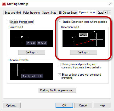
- If you do not typically work with Dynamic Input turned on, you will want to to have it on when using this command, as that will allow you to key in the spacing value; otherwise, you will need to use the Pick array distance command line option and then pick two points to define the spacing value. Verify that the Enable Dimension Input where possible toggle is checked on the Dynamic Input tab of the Drafting Settings dialog and that Dynamic Input is enabled (DYNMODE system variable is set to 2 or, if you also want pointer input, 3). With Dynamic Input so enabled, you will see a dimensional input on the screen when you are in the command, and can change the value on the fly and see the potential effect on screen before committing to the array.

- The initial prompt, Select an edge to array from or Enter to pick two points:, is asking you to define a line in the drawing. The array will run perpendicular to this line, so, for objects that are anchored to a Wall, you will want this line to be perpendicular to the Wall, so that the array projects out along the length of the Wall. A jamb line would be an appropriate choice; just hover your cursor over one until you see the highlight line, then left click to select that line. If you prefer, you can press the ENTER key and then select two points in the drawing to define the "edge to array from".
- Once the "edge to array from" is established, you will be prompted to "Drag out array elements" or choose one of the command line options. The initial spacing value and spacing method will be whatever was used for the previous use of the command. Moving your cursor away from the edge by the spacing amount will result in a two-element array; as you move the cursor even farther away, additional elements will be added. Preview graphics, in the form of a bounding box indicating the overall extents of the arrayed object(s), will show you what you will get at the current cursor position. Selecting a point when you have what you want will end the command and create the array.
- As previously noted, you can key in a spacing value to set the distance at which the array elements are spaced, if Dynamic Input is turned on and Dimension Input is enabled. The preview graphics will update accordingly.
- There are two different ways in which the spacing value is applied, and you can choose one of the two command line options to select the desired method. The Offset method arrays the elements such that the distance from a given point on one object to the same point on the next instance of that object is the spacing value. The dimension of the arrayed item(s) in the direction of the array is included within the spacing value. The Clear distance method arrays the selected objects such that the distance between the objects in the direction of the array is the spacing value. The dimension of the arrayed item(s) in the direction of the array is added to the spacing value..
- The Pick array distance command line option can be used to set the spacing value by picking points in the drawing canvas, rather than keying in a value. This can be useful if you want the spacing value to match a distance that is already constructed in the drawing, particularly if it is not a nice, round number. It can also be used if you do not want to enable Dynamic Input.
- The Enter count command line option allows you to key in the number of instances in the final array, rather than setting this by dragging your cursor on screen. This can be useful if you have a relatively large number of items in the array, and do not want to count the items in the on-screen preview to be certain you have the right amount. The initial default value for the count will be based on how many items are currently in the array based on the cursor position and spacing value. Note that once you set the count number, the command will finish and the array will be created, so be certain to have the desired spacing value and spacing method set prior to using the Enter count command line option.
- The Clear distance spacing method uses the overall dimension of the arrayed object(s), which may or may not be the "Width" dimension for a Door or Window. If the "Measure to" property of a Door or Window is set to Inside of frame, as my firm does with Doors, then you will need to take into account the additional width of the frame component at each jamb when determining the spacing value when the Clear distance method is used.
Subscribe to:
Posts (Atom)