- Identify the property[ies] you wish to display in your tag, and the Property Set Definition[s] that contain that[those] property[ies], along with any other Property Sets that you would like to have your tag attach. Create any new Property Set Definitions and/or copy existing ones to the file in which you will create the tag. This can be any drawing file for learning/experimental purposes, but when you are creating “final” tags, you will want to either use the out-of-the-box Schedule Tables (Imperial).dwg or create a tag source file to hold your office’s custom tags. This file also serves as the central repository for Property Set Definitions and Schedule Table Styles, and needs to be accessible to all who will use the Tool palette tool you create for your tag.
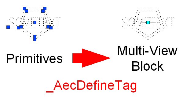
- In your source file, draw the graphics you want for the tag, using text placeholders where you want to display property data. Keep in mind that the tags will use annotation scaling, so make any placeholders you want to plot at the annotation plot size one unit high. Scale other placeholders and graphics accordingly. The string you use in your placeholder text will become the default text for the attribute definition the text will become, so choose your string with that in mind. Figure 1 below shows the primitive graphics on the left, a single piece of middle center justified text, one unit high, and two five-sided closed lwpolylines. The final tag is shown on the right. (Note: you can click on any of the pictures to see a larger, clearer version. Use the Back button on your browser to return to the post.)
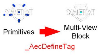
Figure 1: Primitive Graphics to Multi-View Block - Start the _AecDefineTag command; the easiest way is to choose Format > Define Schedule Tag… from the pulldown menus. Select your graphics, as directed by the command line prompt. The Define Schedule Tag dialog appears as shown in Figure 2.

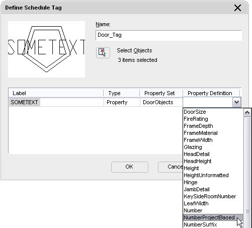
Figure 2: The Define Schedule Tag dialog - The Define Schedule Tag dialog will show a preview image of your tag in the upper left corner. To the right of that, the Name edit box allows you to give your tag a name; the same name will be used for both the view block and the Multi-View Block for your tag. There is also a Select Objects button, to allow you to change the graphics to be included in your tag. Enter a name for your tag (see Figure 3).
- Below the preview graphics and the Select Objects button is a list box that shows each placeholder text item you included in your selection set. The Label column will initially show the text string of the placeholder text. If you leave a text item “as is”, it will be static text in the view block. To get your placeholder text to be converted to a properly formatted attribute definition in the view block, click where it says “Text” in the Type column on the row of a particular placeholder, and select Property in the dropdown list, as shown in Figure 3.

Figure 3: Entering a name and changing the Type to Property Move over to the Property Set column, and choose the Property Set that includes the property you want want this placeholder to display (Figure 4). Finally, choose the property name in the Property Definition column (Figure 5). Notice that the Label has now changed to the PropertySetName:PropertyName format that will be used for the attributed defintion tag, which will be familiar to those who have created tags in prior releases (Figure 6). Repeat this process for each placeholder text you included in your tag graphics.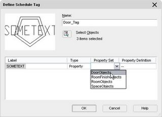
Figure 4: Selecting the Property Set
Figure 5: Setting the Property Definition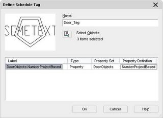
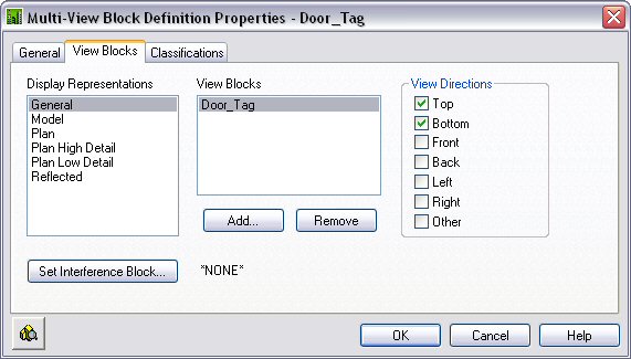
Figure 6: The Label is now formatted - When you are certain that all of the graphics are included and all of the placeholder text has been set to the correct property, select the OK in the Define Schedule Tag dialog and, following the Command line prompt, pick the point that will be the insertion point of your tag, relative to the selected graphics. The graphics are replaced with a Multi-View Block that contains a view block showing your graphics, and one or more attributes – one for each placeholder text that you converted to a property, see Figure 1 above. Save the file so that you can make a tool. Select the Multi-View Block, right click and choose Edit Multi-View Block Definition... from the context menu. Select the View Blocks tab and note that the view block created has been assigned to the top and bottom view directions for the General Display Representation for Multi-View Blocks, as indicated in Figure 7. Select the Cancel button to close the dialog without making any changes.
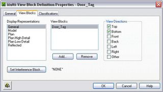
Figure 7: The View Blocks tab of the newly created Door_Tag MVB - Set an editable Tool palette current, then select the newly created Multi-View Block. Right-click and drag the Multi-View Block onto the tool palette. Edit the new tool’s properties, and set the layer key you want associated with the tool, and make any other settings. You are now ready to use your new tag. Figure 8 shows a door tagged with the example tag.

Figure 8: A tagged door
March 21, 2005
ADT 2006 Tags Illustrated
There was a glitch with the Hello BloggerBot yesterday that prevented me from including all the wonderful illustrations I had prepared for my previous post. Now that it has been cleared up, here is the tutorial, complete with illustrations.





March 20, 2005
ADT 2006 Tags
If you can draft in AutoCAD, you can make an ADT tag in 2006.
The process of creating tags has been made much simpler in ADT 2006. You can avoid the AEC Content Wizard altogether for basic tags, and just use the new tag wizard. You do not even need to create a view block or a multi-view block - just place text "placeholders" where you want to display property data and draw the rest of your graphics.
Here is a quick tutorial on how to create a tag in Autodesk® Architectural Desktop 2006 using the new _AecDefineTag command:
The process of creating tags has been made much simpler in ADT 2006. You can avoid the AEC Content Wizard altogether for basic tags, and just use the new tag wizard. You do not even need to create a view block or a multi-view block - just place text "placeholders" where you want to display property data and draw the rest of your graphics.
Here is a quick tutorial on how to create a tag in Autodesk® Architectural Desktop 2006 using the new _AecDefineTag command:
- Identify the property[ies] you wish to display in your tag, and the Property Set Definition[s] that contain that[those] property[ies], along with any other Property Sets that you would like to have your tag attach. Create any new Property Set Definitions and/or copy existing ones to the file in which you will create the tag. This can be any drawing file for learning/experimental purposes, but when you are creating “final” tags, you will want to either use the out-of-the-box Schedule Tables (Imperial).dwg or create a tag source file to hold your office’s custom tags. This file also serves as the central repository for Property Set Definitions and Schedule Table Styles, and needs to be accessible to all who will use the Tool palette tool you create for your tag.
- In your source file, draw the graphics you want for the tag, using text placeholders where you want to display property data. Keep in mind that the tags will use annotation scaling, so make any placeholders you want to plot at the annotation plot size one unit high. Scale other placeholders and graphics accordingly. The string you use in your placeholder text will become the default text for the attribute definition the text will become, so choose your string with that in mind.
- Start the _AecDefineTag command; the easiest way is to choose Format > Define Schedule Tag… from the pulldown menus. Select your graphics, as directed by the command line prompt. The Define Schedule Tag dialog appears.
- The Define Schedule Tag dialog will show a preview image of your tag in the upper left corner. To the right of that, the Name edit box allows you to give your tag a name; the same name will be used for both the view block and the Multi-View Block for your tag. There is also a Select Objects button, to allow you to change the graphics to be included in your tag. Enter a name for your tag.
- Below the preview graphics and the Select Objects button is a list box that shows each placeholder text item you included in your selection set. The Label column will initially show the text string of the placeholder text. If you leave a text item “as is”, it will be static text in the view block. To get your placeholder text to be converted to a properly formatted attribute definition in the view block, click where it says “Text” in the Type column on the row of a particular placeholder, and select Property in the dropdown list. Move over to the Property Set column, and choose the Property Set that includes the property you want want this placeholder to display. Finally, choose the property name in the Property Definition column. Notice that the Label has now changed to the PropertySetName:PropertyName format that will be used for the attributed defintion tag, which will be familiar to those who have created tags in prior releases. Repeat this process for each placeholder text you included in your tag graphics.
- When you are certain that all of the graphics are included and all of the placeholder text has been set to the correct property, select the OK in the Define Schedule Tag dialog and, following the Command line prompt, pick the point that will be the insertion point of your tag, relative to the selected graphics. The graphics are replaced with a Multi-View Block that contains a view block showing your graphics, and one or more attributes – one for each placeholder text that you converted to a property. Save the file so that you can make a tool.
- Set an editable Tool palette current, then select the newly created Multi-View Block. Right-click and drag the Multi-View Block onto the tool palette. Edit the new tool’s properties, and set the layer key you want associated with the tool, and make any other settings. You are now ready to use your new tag.
For single view block tags, the new command takes care of everything. If you want to set up scale-dependent tags that do not use annotation scaling, you will have to use the Create AEC Content wizard, as in previous releases.
Additional cool features:
- ADT now recognizes tags as tags, not just as a Multi-View Block. So not only can you release the anchor of a tag, you can now re-anchor the released tag if you like, rather than erasing and re-tagging. This works for any legacy tags you have, too - you do not need to recreate any customizations you made in previous releases.
- You can right click an existing tag and choose Add Selected to use the same tag on a new object.
- With the new AecDefineTag command, you do not have to remember either the exact spelling of your Property Set Defintion name or that of the property name – nor do you have to type them correctly.
- You can specify additional property sets to be attached by the tool, without creating invisible attributes in your tag.
- You can use a variation on the tag tool to create a tool that will attach property set definitions without attaching a tag. This can be useful when you want to add a Property Set with a location grip to objects in an Element, but do not want to add a tag.
March 16, 2005
ADT 2006 Discussion Group Opens
A new discussion group for the soon-to-be-released Autodesk Architectural Desktop 2006 is now open. You can access this discussion group by either a web browser or
a newsreader.
a newsreader.
February 21, 2005
ADT 2005 0 kb DST File HotFix
Chris Yanchar has announced the availability of a HotFix for ADT 2005 - 0 KB DST problem in the ADT 2005 Discussion Group. The HotFix can be downloaded from the Autodesk website.
February 15, 2005
Matt Dillon on Out-of-the-Box Standards
Once again, Matt has posted a "must read" article for anyone using ADT and starting to set up standards or re-examining current standards. Those intending to use the United States National CAD Standard as a basis for their own office standard can take advantage of the US NCS Version 2.0 compliance of the out-of-the-box content, as described by Matt in his ADT Standards Out of the Box for U.S. Users blog article.
February 08, 2005
Perkins + Will Georgia Tech Computer Science Building
On Thursday, February 17, 2005, 11 a.m. PST / 2 p.m. EST, Autodesk is hosting a webcast featuring the use of ADT for the design of the computer science building at Georgia Tech, by Perkins + Will. Sign up for the webcast by clicking on this link.
February 04, 2005
Removing Unsightly Bottom Frames at Doors
Ever use a Door/Window Assembly to model a door with an integral sidelight and/or transom? Ever wish you had not done so, because you just can not get rid of the lines that make it look like there is a bottom frame at your door opening? Or maybe you got rid of those lines, only to lose the frame at the sidelight? And to make matters worse, the pesky frame is still there in that grand rendering you had planned? If so, read on.
First off, let me note that I tested the following in Architectural Desktop 2004, and the same principals apply in 2005. My memory is fuzzy on this, but I do not believe you can do all the things noted below in 3.3. For 3.3, you need to turn off the entire bottom frame of the Window Assembly [as they were called in that release] by not assigning a frame to the bottom location, then "simulate" a bottom frame at the sidelight by creating an infill panel with a width that matches the mullion width. The out-of-the-box styles use this technique; you can reverse engineer it from one of those.
The first thing to realize - assuming that you are using the out-of-the-box display settings - is that the two lines that appear to be the bottom frame in a Door/Window Assembly are in fact not that, but the Sill A and Sill B components of the Sill Plan display. Those of you who managed to turn off those lines already know that. You have a choice to make here. If most of your Door/Window Assemblies are in exterior walls and the doors would have thresholds, then you may want to keep the drawing default display settings as is - with Sills A and B turned on, and apply style overrides to your interior Door/Window Assemblies to turn them off. If the converse is true, you may choose to turn off the sills in the drawing default, and use style overrides for your exterior styles.
So now your door panel looks great in plan, but you only have the glass lines at the sidelight. What you need to do now is edit the Plan Display Representation and turn on the Below component.
April 29, 2005 Update: Unanchored Door/Window Assemblies will not display the frame lines even after the Below Component is turned on. You will need to set a "manual above and below cut plane height" on the Other tab of the Plan Display Representation at a height that passes through your frame or mullion below. This is not necessary with Door/Window Assemblies that are anchored to a wall.
Again, you can do this either at the drawing default level or as a style override. You will now either see a frame [or, if you have a mullion in the sidelight below the cut plane, the mullion] all the way across your assembly, or, if you did not assign a frame to the bottom location in your assembly style, you will continue to see nothing. Should you have a mullion below the cut plane at the sidelight, you may have just what you want in plan view - but chances are you are not getting the 3D view correct - unless you are using the 3.3-era technique of simulating the bottom frame with a wide panel as noted above. There is nothing wrong with that - but consider the following as an alternate, and perhaps cleaner way to model that bottom frame.
What you need to do is make certain you have a bottom frame defined, then override that frame by removing it from any cells with doors or other infills where you do not want to have a bottom frame. The following steps outline the procedure.
First off, let me note that I tested the following in Architectural Desktop 2004, and the same principals apply in 2005. My memory is fuzzy on this, but I do not believe you can do all the things noted below in 3.3. For 3.3, you need to turn off the entire bottom frame of the Window Assembly [as they were called in that release] by not assigning a frame to the bottom location, then "simulate" a bottom frame at the sidelight by creating an infill panel with a width that matches the mullion width. The out-of-the-box styles use this technique; you can reverse engineer it from one of those.
The first thing to realize - assuming that you are using the out-of-the-box display settings - is that the two lines that appear to be the bottom frame in a Door/Window Assembly are in fact not that, but the Sill A and Sill B components of the Sill Plan display. Those of you who managed to turn off those lines already know that. You have a choice to make here. If most of your Door/Window Assemblies are in exterior walls and the doors would have thresholds, then you may want to keep the drawing default display settings as is - with Sills A and B turned on, and apply style overrides to your interior Door/Window Assemblies to turn them off. If the converse is true, you may choose to turn off the sills in the drawing default, and use style overrides for your exterior styles.
So now your door panel looks great in plan, but you only have the glass lines at the sidelight. What you need to do now is edit the Plan Display Representation and turn on the Below component.
April 29, 2005 Update: Unanchored Door/Window Assemblies will not display the frame lines even after the Below Component is turned on. You will need to set a "manual above and below cut plane height" on the Other tab of the Plan Display Representation at a height that passes through your frame or mullion below. This is not necessary with Door/Window Assemblies that are anchored to a wall.
Again, you can do this either at the drawing default level or as a style override. You will now either see a frame [or, if you have a mullion in the sidelight below the cut plane, the mullion] all the way across your assembly, or, if you did not assign a frame to the bottom location in your assembly style, you will continue to see nothing. Should you have a mullion below the cut plane at the sidelight, you may have just what you want in plan view - but chances are you are not getting the 3D view correct - unless you are using the 3.3-era technique of simulating the bottom frame with a wide panel as noted above. There is nothing wrong with that - but consider the following as an alternate, and perhaps cleaner way to model that bottom frame.
What you need to do is make certain you have a bottom frame defined, then override that frame by removing it from any cells with doors or other infills where you do not want to have a bottom frame. The following steps outline the procedure.
- Place a instance of your Door/Window Assembly in the drawing using the DoorWinAssemblyAdd command, or a tool - use the generic Door/Window Assembly tool if you do not have one set up for this purpose. Set the length and height to values appropriate to the style.
- In an elevation or isometric view, select the Door/Window Assembly, right click and choose Infill > Show Markers from the context menu. A magenta cell icon should appear in each cell.
- Select the assembly again, right click and choose Infill > Override Assignment... from the context menu. You will be prompted to "Select infill to override". Select the infill marker in the door cell and press Enter.
- In the Infill Assignment Override worksheet, place a checkmark in the Bottom toggle in the Frame Removal area. Select OK. The bottom frame will disappears from the door cell .
- That takes care of that single instance, but we are not done yet. After all, who wants to go through that every time you place one of these assemblies? Select the assembly, right click and choose Design Rules > Transfer to Object from the context menu.
- Select the assembly again, right click and choose Design Rules > Save to Style... from the context menu.
- In the Save Changes worksheet, you can save the overrides you made to this instance to a style. You have the option to save them to any existing Door/Window Assembly style in the drawing - including the current style of the selected assembly, the default choice, or you can create a new style. You can also choose which types of overrides to save to the style. If your style did not previously have any overrides, the infill override will be the only toggle active - the others will be grayed out. Place a checkmark in the "Transfer Infill Overrides to Style" toggle. If there were other overrides and you want to keep them, check the other active toggles as well, then select OK.
- Add a new instance of your modified style and look at it from various vantage points to confirm that the overrides are now part of the style. Edit the Door/Window Assembly style and click on the Overrides tab. Expand the Infill Assignments category, which now has a "+" next to it, to see your newly created infill override. You can look at and even remove the override here [right click the name], but you can not create one here.
If you like, you can find a sample file in which I have done the above, in the Autodesk Architectural Desktop 2004 Discussion Group, in a thread titled "window assembly". In the sample file, there are two Door/Window Assembly styles, Style1 and Style2. Style1 is the starting point, without the override; Style2 is the finished style, with the override at the door cell. The post that has the attachment has a version of the above tutorial, with the directions specific to the sample file.
January 29, 2005
VBScript Operators for Formula Properties
Autodesk® Architectural Desktop formula properties are evaluated as VBScript expressions. VBScript has a number of operators, falling into four categories: arithmetic, concatenation, comparison and logical. Descriptions of those that, in my opinion, are most likely to be used in a formula property can be found below. Hard core programmers who want to push the envelope of what can be done in a formula should probably acquire a reference or two on VBScript. I have found VBScript in A Nutshell, A Desktop Quick Reference, 2nd Edition, by Paul Lomax, Matt Childs & Ron Petrusha, quite useful. It has way more on VBScript than you likely need to know for writing formula properties, but the reference section contains a listing of the available commands and their use.
Arithmetic Operators
Used to manipulate numeric values.
+
Adds two numbers. Can also be used to concatenate strings, but use the concatenation operator [see below] to avoid confusion.
-
Subtracts two numbers, or indicates a negative value.
/
Divides two numbers, returning a floating point number.
*
Multiplies two numbers.
\
Divides two numbers, returning an integer – without a remainder or decimal places.
Mod
Modulo operator, divides two numbers and returns only the remainder; the original numbers are rounded to integers before performing the operation.
^
Raises a number to the power of an exponent. The number is first, followed by the “^” and then the exponent.
String Operator
Used to join individual strings into one string.
&
Concatenates two strings. Non-string values are converted to strings and then concatenated.
Comparison Operators
Used to compare two expressions, these operators return True, False or Null [only when both expressions are Null]. The first expression precedes the operator, and the second follows it. These are frequently used with If Then [ElseIf] [Else] End If statements to provide alternate formula results based on values stored in other properties [or derived from other properties].
>
Greater than, True if the first expression is greater than the second.
<> or ><
Not equal, True if the first expression is either less than or greater than the second.
>= or =>
Greater than or equal, True if the first expression is greater than or equal to the second.
<= or =<
Less than or equal, True if the first expression is less than or equal to the second.
=
Equal, True if the first expression is equal to the second.
Comparison operators work on both numeric and string values. When mixing these in a single comparison, the comparison is done in accordance with the following:
Arithmetic Operators
Used to manipulate numeric values.
+
Adds two numbers. Can also be used to concatenate strings, but use the concatenation operator [see below] to avoid confusion.
-
Subtracts two numbers, or indicates a negative value.
/
Divides two numbers, returning a floating point number.
*
Multiplies two numbers.
\
Divides two numbers, returning an integer – without a remainder or decimal places.
Mod
Modulo operator, divides two numbers and returns only the remainder; the original numbers are rounded to integers before performing the operation.
^
Raises a number to the power of an exponent. The number is first, followed by the “^” and then the exponent.
String Operator
Used to join individual strings into one string.
&
Concatenates two strings. Non-string values are converted to strings and then concatenated.
Comparison Operators
Used to compare two expressions, these operators return True, False or Null [only when both expressions are Null]. The first expression precedes the operator, and the second follows it. These are frequently used with If Then [ElseIf] [Else] End If statements to provide alternate formula results based on values stored in other properties [or derived from other properties].
>
Greater than, True if the first expression is greater than the second.
<> or ><
Not equal, True if the first expression is either less than or greater than the second.
>= or =>
Greater than or equal, True if the first expression is greater than or equal to the second.
<= or =<
Less than or equal, True if the first expression is less than or equal to the second.
=
Equal, True if the first expression is equal to the second.
Comparison operators work on both numeric and string values. When mixing these in a single comparison, the comparison is done in accordance with the following:
- If both the string and number are “literal” – actually written, not through a variable, then the string is converted to a number prior to comparison.
- If one is literal and the other is a variable, the variable value is converted to the type of the literal value prior to conversion.
- If both are variables, the number will be evaluated as smaller than the string.
Logical Operators
Used to evaluate one or more expressions, returning a logical value [True/False/Null]. For example, a logical operator can be used to have two conditions evaluated for a single If statement. These can also be used as bitwise operators. If you are doing this in a formula property, you really do not need to read this article.
And
Evaluates to True if both expressions are True, otherwise, False.
Or
Evaluates to False when both expressions are False, otherwise, True.
Not
Negates a single expression. If the expression is True, Not evaluates to False; if the expression is False, Not evaluates to True.
Eqv
Evaluates to True if both expressions are True or both are False; evaluates to False if one is True and the other False.
Xor
Evaluates to True if one is True and the other False; evaluates to False if both expressions have the same evaluation.
There is an order of precedence for evaluating operators when more than one appears on the same line. I so strongly recommend using parentheses to make your desired order of operation explicit that I am going to omit describing the VBScript hierarchy.
January 25, 2005
Matt Dillon on Automating Project Startup
In case you have not been following the thread in the Autodesk Architectural Desktop 2005 Discussion Group, Matt has generously shared his knowledge of automating the setup of Projects in ADT in this article in his blog.
January 23, 2005
Changing A Drawing's Plot Style Type
There are two types of plot styles: color-dependent plot styles [CTB extension] and named plot styles [STB extension]. When plotting, you will only see plot styles of the type the drawing you are plotting is set to use. If you are not seeing your plot style file, and you are certain that it is in the plot style folder [check this in the Options dialog, on the Files tab], then you likely have a file that is set to use the other type of plot style files. Verify this by opening the Properties toolbar in Autodesk® Architectural Desktop 2004 or 2005 and examining the rightmost control, for Plot Style. With no active command, if it is grayed out and displaying “ByColor”, you are in a color-dependent plot style file. If it is not grayed out and you can click on the arrow to see a list of plot styles, you are in a named plot style file.
STB to CTB: Type CONVERTPSTYLES at the Command: prompt to convert your file to use color-dependent plot styles.
CTB to STB: You will need a conversion file to map your layers [by color] to a named plot style. If your office migrated from CTBs to STBs, you may already have one of these, based on your old CTB file; if you can access that, use it and skip the CONVERTCTB step that follows. Type CONVERTCTB at the Command: prompt and select a CTB file, to create a translation file. Then type CONVERTPSTYLES and select your translation file. NOTE: This will convert the file to use STB plot styles, but will assign plot styles to layers based on their color and the corresponding named plot style in the translation file. You will likely need to reassign plot styles, based on the STB file with which you wish to plot.
How to avoid the above mess? Set up template files - or use the out-of-the-box ones - that use your desired plot style type and make certain all new files are started using one of these templates. You can also set your plot style type preference in the Options dialog [Plotting tab], but this will only cover drawings started without a template ["from scratch"], which is generally not a good idea in Autodesk® Architectural Desktop, or when opening a pre-AutoCAD 2000 file, which was before the introduction of plot styles.
STB to CTB: Type CONVERTPSTYLES at the Command: prompt to convert your file to use color-dependent plot styles.
CTB to STB: You will need a conversion file to map your layers [by color] to a named plot style. If your office migrated from CTBs to STBs, you may already have one of these, based on your old CTB file; if you can access that, use it and skip the CONVERTCTB step that follows. Type CONVERTCTB at the Command: prompt and select a CTB file, to create a translation file. Then type CONVERTPSTYLES and select your translation file. NOTE: This will convert the file to use STB plot styles, but will assign plot styles to layers based on their color and the corresponding named plot style in the translation file. You will likely need to reassign plot styles, based on the STB file with which you wish to plot.
How to avoid the above mess? Set up template files - or use the out-of-the-box ones - that use your desired plot style type and make certain all new files are started using one of these templates. You can also set your plot style type preference in the Options dialog [Plotting tab], but this will only cover drawings started without a template ["from scratch"], which is generally not a good idea in Autodesk® Architectural Desktop, or when opening a pre-AutoCAD 2000 file, which was before the introduction of plot styles.
Subscribe to:
Posts (Atom)