If you installed the ADT as AutoCAD shortcut and use it, you may have become familiar with the out-of-the-box AutoCAD Tool palette tools, and wish you had access to them when running ADT as ADT. If so, read on.
When I first tackled this problem, I discovered that I could run ADT as AutoCAD to get the AutoCAD Tool palettes on screen. Then I opened the Content Browser, which is a separate program and can be run independently of ADT. [The executable, AecCB47.exe, is located in the same folder as the acad.exe file, C:\Program Files\Autodesk Architectural Desktop 2006 in the default installation location.] I created a catalog, created palettes within it, and laboriously cut and pasted the tools from each palette. Afterwards, I got smarter and came up with the following:
- Start ADT as AutoCAD.
- Open the Options dialog, and go to the Files tab.
- If necessary, scroll down until you see the Tool Palettes File Locations category.
- Expand that category, and make note of the location where the AutoCAD tool palettes are stored.
- Close the Options dialog, and close ADT as AutoCAD.
- Start ADT as ADT.
- Open the Options dialog, go to the Files tab and expand the Tool Palettes File Locations category.
- Click on the Add… button.
- Click on the Browse… button and navigate to the folder where the AutoCAD tool palettes are stored. Leave this at the bottom of the list.
- Click on the OK button to exit the Options dialog, saving your changes.
- If necessary, change the current Palette Group to All Palettes, and you should be able to access the AutoCAD tool palettes.
At this point, if you wish, you can open the Content Browser, create a catalog, and drag-n-drop the AutoCAD tool palettes to the catalog. That is much easier than copying the tools on each palette to the clipboard and pasting them into a tool palette in the Content Browser, one palette at a time. Once you have the palettes it an ADT Tool catalog, you may, if you wish, go back into the Options dialog and delete the path to the AutoCAD tool palettes location, then i-drop them into your current workspace. That will set up a separate copy of the tool palettes, so if you plan to edit them, you may simply want to keep using them in the out-of-the-box location.
Note also that, when I did this using either method, the graphics for the tools when brought into ADT were not as crisp as they were in AutoCAD. You could always create new images and apply them in ADT if you really wanted to do so – I am not certain what impact that would have when running ADT as AutoCAD, so you may want to do that on a copy of the palettes.
New to ADT 2006 is the ability to export tool palette groups to an external file, with an extension of XPG. This file can then be copied to another machine and imported there. You could also export tool palette groups you no longer need, but want to save in case you need to restore them in the future.
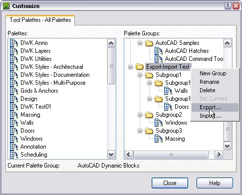
To export a tool palette group, right click on the spine of the Tool palettes and choose Customize... from the context menu. On the right side of the Customize dialog, in the Palette Groups list box, right click on a tool palette name and choose Export... from the context menu.
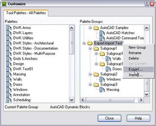
In the Export Group dialog, navigate to the folder in which you wish to store your XPG file, provide a name and select Save to create the file. The palette group you select, and any nested palette groups will be included in the exported file.
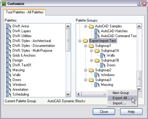
To export all of the palette groups, scroll down to the bottom of the Palette Groups list box and right click below the bottom line. Choose Export All... from the context list and save the file as noted above. All of the palette groups will be included in the exported file.
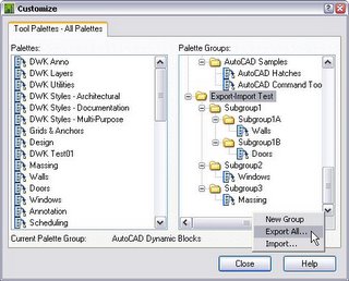
Importing palette groups is similar; right click a palette group or below the entire list and choose Import... from the context menu. Navigate to the desired XPG file and choose Open to import the palette group[s].
Note that this does not export or import the tool palettes associated with each group, so you can not share the actual palettes this way. I have found that if I import a palette group back onto the same computer where the palettes remain in the active profile, the palette groups are populated with the palettes, so it does "remember" which palettes were in each group. If you do this in a different profile, with a different tool palette workspace that does not have the same palettes, the groups will not be populated.
I do not have access to multiple computers that have ADT 2006 installed, so I do not know exactly how the groups are saving the list of palettes associated with each group, but I suspect it may be using the globally unique identifier [GUID] assigned to each palette. If the GUIDs of refreshable pallete pulled from the same, network-based catalog are the same, and those palettes are loaded on two different computers, you should be able to export the palette groups on one computer and import them on the other and have them be populated with the tool palettes. Unfortuately I can not test that suspicion to see if it holds true, or whether it is necessary to have the palettes installed before importing the palette groups.
Can it really be an entire year since I started this blog? The calendar says so, but it does not seem like it to me. Best of luck to all of you who are attending Autodesk University this year. I am not going this year, but hope to do so again in the future.
For those not going, but looking to improve their ADT skills, check out the AUGI Training Program course on Door/Window Assemblies offered this month by Steve Bennett.
ADT will report NA for an automatic property when that property does not have a value assigned for a particular object or style. The actual text displayed in controlled by the Property Data Format assigned to the property on the Formatting tab, in the General section, in the Not Applicable edit box. When reading a property that could have such an "empty" value into a formula property, VBScript will interpret the value as being "Empty", the formatting applied in the Property Data Format will not follow through. You can not test the value of the automatic property for "NA", or whatever string you assign to it. Update, 9/3/2006: If you enclose the text in the Not Applicable edit box in the Property Data Format with explicitly typed double quotation marks, the string value will be returned, rather than "Empty". See this article for additional information on this.
Attempting to perform mathematical operations, or even to convert the value to a particular type [using the CDbl function, for example] will result in an error and the formula will fail.
One solution for this, assuming the original automatic property has a numeric value when a value is assigned, would be to create an intermediate formula that uses either the VBScript TypeName or VarType function to test the automatic property value to see if it holds an empty value [TypeName returns the string "Empty"; VarType returns the integer 0]. If it does, have the RESULT of the formula be a number that is either meaningful to an "Empty" condition, or is at least unique - meaning that it would not be used when a numeric value is assigned. Then you can use the value of the intermediate formula in your final formula, testing, if necessary, for the value assigned for the "Empty" condition and taking the appropriate action.
A sample file demonstrating this condition and solution can be found in this thread in the Autodesk Architectural Desktop 2005 Discussion Group. The automatic property in question here is the door thickness. For cased opening door styles [using the Pass Through door type], there is no door, and the thickness property is "Empty" for doors using the Pass Through type. The request was to be able to have the thickness of existing doors show as "--" on the schedule while having the thickness show for new doors. The problem was the formula would fail when a new cased opening was scheduled, as applying the CDbl to the value of the automatic property in the formula property [to force whole numbers to be interpreted as reals] does not work when the value is empty.
The intermediate property in the example file, ThicknessForFormula, sets its value to 0 if the automatic property is "Emtpy", otherwise it passes through the value of the automatic property without doing anything to it. If there is no door leaf, then 0 would seem to be an appropriate value for the thickness. The final formula, ThicknessForSchedule, then tests that value and I chose to display "--" in the schedule if it is zero, otherwise the value is forced to be a double and the Length - Short Property Data Format is applied to get imperial architectural formatting.
The first level of control over which items appear in your schedule is by setting up the appropriate object types on the Applies To tab of the Schedule Table Style. You can further control the objects of those object types that are to appear in your schedules without laboriously selecting individual items – which is not even possible when scheduling through externally referenced files or through an external drawing – by filtering out unwanted items. You can set up filters in two different ways:
1. Layer Filter: This is applied to each individual instance of a schedule, in the Properties palette. It requires that you have placed items to be scheduled and items not to be scheduled on separate layers. You will need to add the layer filter every time you add a new schedule table. If you are scheduling through an externally referenced file, be certain that your layer filter includes the layer on which the Xref is inserted and also includes the externally referenced layer names. For example, if you have a file called A01.dwg that has doors you wish to schedule, those doors are on layer A-Door-N and that file is externally referenced into another file, on layer A-Anno-Refr-N, where you will be generating your door schedule, then your layer filter may want to be something like
*A-Door-N,A-Anno-Refr-N.
You can include multiple filters in the layer filter – separate each with a comma.
2. Classifications: You can set a classification filter on the Applies To tab of the Schedule Table Style. This will apply to all instances of the schedule, without any further action on your part. Note that you must have your Classification Definition in the file with your Schedule Table Style prior to trying to set a Classification filter.
Classifications are assigned at the style level, so they only work for ADT objects that have styles/definitions. They will not work for AutoCAD objects, including block references. For classifications to work, you need to have separate object styles for objects to be scheduled and objects that are not to be scheduled. [In other words, you can not use the same style for two objects, one to be scheduled and the other not to be scheduled.]
The Classification Definition you use should have at least two classifications defined within it. One [or more] classification[s] would be assigned to the objects to be scheduled and one [or more] classification[s] would be assigned to the other objects. You could have just one classification, for objects to be scheduled, and leave the unscheduled objects unclassified, but that may cause problems down the line, when you or someone else working on the project tries to remember/determine whether a style was intentionally not classified so as not to be scheduled or was simply either overlooked or added after the initial schedule was created.
Exactly how you should set this up depends upon whether you want to use the same Classification Definition for other purposes. One method that others have recommended here is to use the out-of-the-box Uniformat classification system, assigning appropriate classifications to each door style, keeping track of those that should be scheduled, then checking only those on the Applies To tab of your Schedule Table Style. Another method, and one which I have used successfully, is to set up a Classification Definition just for scheduling, with two classifications: Schedule and NoSchedule. This makes the intent very clear; if you have need to use the out-of-the-box Uniformat classifications or one of your own for other purposes, you can attach that along with the one for scheduling, and need not worry about which of those classifications are scheduled and which are not.
As reported by Shaan Hurley in his Between the Lines blog, Autodesk has released a free DWG viewer. The viewer reportedly also supports ADT and ABS custom objects - the object enablers are built in. Read more in Shaan's post or get the download here.
I read an interesting article by Tomislav Zigo a few weeks ago about Building Information Modeling. What intrigued me most was the idea of being able to take a firm’s accumulated knowledge and embed it into the objects in the information model, so that new hires or less experienced staff could take advantage of that knowledge. The article includes a sample file showing how property data could be used to create spaces and objects – in this case, Multi-View Blocks – that “know” whether a particular object belongs in a particular space. The sample file uses a schedule table to list the Multi-View Block objects and report whether the block is “allowed” in the space in which it was placed.
I found the sample file fascinating, but thought that in a file of “real project” size, that using a schedule table might be a little cumbersome. You would likely end up placing all of the objects, then generating the schedule and back-checking for items incorrectly placed. It occurred to me that having immediate, or near immediate feedback would improve the workflow. This seemed like just the excuse I needed to try out Display Themes, a feature added with the 2006 release.
I have posted a sample file of my own, in the Autodesk Architectural Desktop Customization Discussion Group. I chose to set up my sample file somewhat differently than the one noted above. Instead of listing all of the objects allowed in a space in the space style, I chose to list the space styles in which an object is permitted in the object’s style/definition. Either approach works – which is better for you depends upon your workflow and the number of different space styles and other objects that you would be including in your system.
Property Set Definitions
As always when dealing with schedule data, the first step is to establish the needed Property Set Definitions. I used style-based property sets – the out-of-the-box SpaceStyles Property Set Definition for the Style property and the custom LocationCheckStyles Property Set Definition – except for the location property that reads the style name from the space into the object’s property data. In Architectural Desktop 2006, the Location property could be part of the LocationCheckStyles Property Set Definition, but, for Multi-View Blocks anyway, the location grip is coincidental with the Multi-View Block insertion point grip, so it can not be moved independently of the block. I also found, when moving the Multi-View Block from room to room, that I had to use the ObjRelUpdate command to manually update the location property, so I chose to set up a separate, object-based Property Set Definition, LocationCheckObjects, to hold the location property. That does mean that you will need to attach the LocationCheckObjects property set to each object – you could set up a tool to do so, and apply it to multiple objects at once. As the goal is immediate feedback, this is not ideal, but I felt that having to attach the object-based property set once was less onerous than having to remember to run ObjRelUpdate every time a particular object was moved from one space to another. The way the formula is set up, the permission will show as “No” if the LocationCheckObjects property set is not attached, so having permission denied no matter where an object is placed should be a clue that the object-based property set is missing. Perhaps future versions of Architectural Desktop will improve the handling of style-based location properties. Remember, these did not work in style-based property sets at all in previous releases.
The LocationCheckObjects has one property, SpaceStyleName. This is a location property that reads in the name of the style of the space on which the object’s location grip is placed; the setting is shown in the image below.
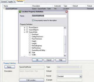
LocationCheckObjects Property Set Defintion and SpaceStyleName Location Property
The LocationCheckStyles Property Set Definition is set up to apply to all styles and definitions, although in the sample file I only used it on Multi-View Block Definitions. There are two properties, PermissionGranted and PermissionList. PermissionList is a text-type manual property that will hold a list of space style names into which a particular object has permission to be placed. A large, “executive” desk, for example, might include Office_Large in its list, but not Office_Small or any of the Workstation styles, as it would not be appropriate to place a desk of that size in a smaller space. The PermissionGranted formula property is where the heavy lifting is done. The VBScript InStr function is used to search the PermissionList manual property, starting at the first character [the first “1” in the parentheses after “InStr”], for an occurrence of the string in the LocationCheckObjects:SpaceStyleName property. The second “1” in the parentheses tells the InStr function to perform a text comparison, rather than a binary comparison. What that means is that the comparison will ignore the case of the text. For example, “a” matches “A” in a text comparison, but does not in a binary comparison. The InStr function returns an integer value under most circumstances – 0 if the string is not found or a positive integer indicating the starting character position in the target string of the first occurrence of the search string. So the formula tests the result to see if it is greater than zero. If so, then the space style name was found in the permission list and the object is permitted; if not, the name was not found [or there was no style name because the object was not placed over a space], and the object is not permitted. The image below shows the properties in the LocationCheckStyles Property Set Definition, as well as the PermissionGranted formula with sample data that returns a result of “YES”.
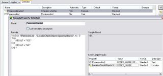
LocationCheckStyles Property Set Definition and PermissionGranted Formula Property
By attaching the SpaceStyles property set to each space style and attaching both the LocationCheckStyles property set to each object style or definition [filling in the PermissionList for each style/definition] and the LocationCheckObjects property set to each object, we can identify whether or not a particular object has been placed correctly. Looking at the Extended Data tab of the Properties Palette to find out whether PermissionGranted for each object is “YES” or “NO” would quickly become tedious. Checking a schedule table would be better, but unless you frequently remove objects from the schedule selection set, would quickly result in a schedule table that would be too big to keep close to the items being added. Display Themes to the rescue! Display Themes allow you to override the “normal” appearance that an object would have for the current Display Configuration and view direction, based on property data attached to the object. This should have great appeal for architects, who are, by and large, a visually oriented group.
Display Theme Style
The Display Theme in the sample file keys on the value in the PermissionGranted property. When the theme is applied, objects whose PermissionGranted value is “YES” will display in color 80 [a bright green]; color 10, a bright red, indicates a “NO” value. Objects that do not have the PermissionGranted property attached will continue to display as they do when the Display Theme is disabled.
Display Themes have styles, like other Architectural Desktop objects, and can be created and edited in the Style Manager, under the Documentation Objects category. In addition to the usual “General” tab, where you can edit the style name and description, Display Themes have three other tabs: Display Rules, where you define the display overrides – “Theme Settings” – and under which conditions each is to be applied – “Theme Rules”; Legend Format, where you set parameters for the Display Theme legend; and Legend Display Properties, where you control the visibility and display of the components of the components of the Display Theme legend.
Design Rules
The main work to be done is on the Design Rules tab. For this relatively simple example, there are two Theme settings, one for when PermissionGranted is “YES”, Index 1 in the image below, and one for when PermissionGranted is “NO”, Index 2.
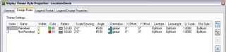
Theme Settings
The hatch parameters in a Theme Setting are only applied if the object has a hatch component turned on. Since Multi-View Blocks do not have a hatch component, the hatch settings have no effect in the sample file and I left them at the initial default values. Note also that I set up the sample Display Theme for on-screen purposes only. I left the Plot Style set to ByBlock, so unless the underlying object was set to plot using the object’s color, the sample file should plot the same whether or not the Display Theme was active. This appears to be the case using Plot Preview; I did not make any actual plots.
The Theme rules here are also quite simple. The LocationCheckStyles:PermissionGranted property holds the value to be shown graphically on the screen. Selecting Index 1 – “Permitted” – in the Theme Settings pane allows you to create Theme Rules for that index. Rule 1.1 states that Index 1 should be applied if the PermissionGranted property is equal to “YES”.

Theme Rules for Index 1 Theme Setting
Selecting Index 2 – “Not Permitted” – allows rules to be created for that index. Rule 2.1 states that Index 2 should be applied if the PermissionGranted property is equal to “NO”.

Theme Rules for Index 2 Theme Setting
Legend Format
Since “YES” and “NO” are the only two values that PermissionGranted can have, the Design Rules are complete. On the Legend Format tab, I set the Title to “Location Check” and the Text Style to “RomanS”, as shown below.
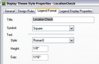
Legend Format
Legend Display Properties
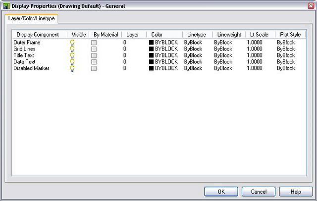
I made no changes to the out-of-the-box settings in the sample file, as shown below.
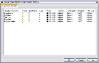
Legend Display Properties
Adding the Display Theme
I chose to add my display theme by setting up a tool, but you can also type _AecDisplayThemeAdd at the Command: prompt, then select the desired style in the Properties Palette. There does not appear to be a command-line option to select or enter the desired style name. A generic Display Theme tool can be found in the Scheduling and Reporting Tool category of the Stock Tool Catalog. i-drop this tool onto an editable tool palette, then edit its properties to reference the desired Display Theme style. For this sample file, I did not bother creating a source file for the style, but you would want to do so for any Display Themes you expect to reuse in other drawings. Have your tool reference the style in the source file by setting the Style location property, after saving the source file to a location that will be available to all who will use the tool.
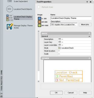
LocationCheck Display Theme Tool and Properties
When adding the Display Theme to a drawing, you will be prompted for the “Upper left corner of display theme:”. This is the upper left corner of the legend – pick an appropriate location. Similar to the prompts for a schedule table, you will then be asked to pick the “Lower right corner of display theme (or RETURN):”. If you pick a point, the legend will be scaled to fit between the two points; if you press ENTER or the space bar, the legend will be scaled according to the current drawing scale and annotation plot size as set in the Drawing Setup dialog. Assuming you have left all the display components turned on, the legend will show the title you entered on the Legend Format tab, along with a list of the Theme Settings accompanied by a square or circle showing the color and hatch pattern assigned to that setting. The Display Theme will also be applied to the current viewport. The legend in the sample file is shown below.
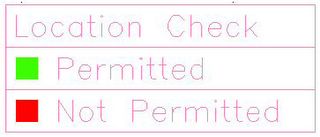
Display Theme Legend
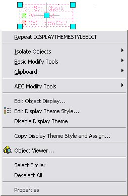
By selecting the legend and right clicking, you have access to a context menu that gives access to editing commands specific to Display Themes. Of particular note is Disable Display Theme, which allows you to turn off the display theme without removing it from the drawing. If you select this, a diagonal slash will appear on the legend [if you leave that component turned on], the display changes set in the theme are deactivated, and the menu item changes to Apply Display Theme, which allows you to turn the theme back on.
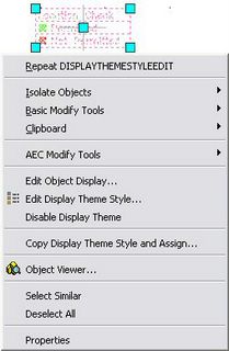
Display Theme Context Menu
The Results
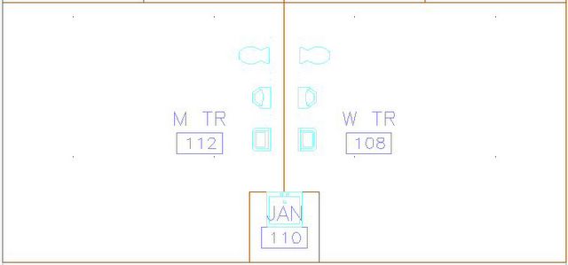
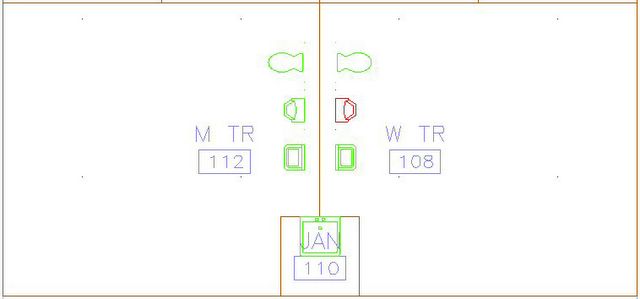
By activating the Location Check Display Theme, you can get immediate feedback on whether a particular object is permitted in a space when moving or copying an existing object, and nearly immediate feedback when adding a new object that already has the LocationCheckStyles property set attached and PermissionList property completed – all you need do is add the LocationCheckObjects property set. The effect is most dramatic when working live in the file, so I would encourage you to download the sample file and try it out for yourself [if you have the 2006 release of Architectural Desktop – Display Themes do not work in prior versions]. Here are two screen shots of the men’s and women’s toilet rooms, each of which has a water closet, urinal and lavatory Multi-View Block. The first shows the out-of-the-box Medium Detail display, the second shows the effect of activating the LocationCheck Display Theme. The PermissionList property for the urinal does not include any of the women’s toilet room Space Style names, and so the instance of the block in the women’s room turns red, flagging it as “Not Permitted”. The other blocks turn green, indicating that they are permitted in the space in which they are placed.
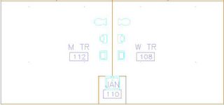
LocationCheck Display Theme Disabled
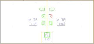
LocationCheck Display Theme Applied

Note that this is not meant to be a finished system, only a proof of concept. Using the space style name as the sole determinant may be too limiting in practice; setting up one or more manual properties in a style-based property set attached to the space style would allow you to have certain key words to identify space types without imposing burdens on the naming of the styles. The formula determining if an object is permitted could also be made more sophisticated, perhaps needing to match only part of the style name and/or splitting out the size [small, medium, large] comparison separately.
Richard Binning has posted the follow up to his July 29, 2005 blog post on copying Layer Keys between two Layer Key Styles. That first post provides a downloadable Excel tool to make comparing two Layer Key Styles easier; the new post (October 3, 2005) includes a VBA routine that allows you to copy Layer Keys between Layer Key Styles. Check out both posts in "beside the cursor...". And thanks to Richard for providing such a useful tool to those of us who VBA challenged.
Beau Turner has unveiled the Triple D Design Wiki, a resource to allow the architectural/engineering community to share their experience using 3D Design software. You can read more about this in his blog, or jump right into the Triple D Design Wiki.
Phase I provides an area for Architectural Desktop users to pool their knowledge. A future Phase II is planned, to suppport Revit Building users.
Here is another opportunity to tap into the accumulated knowledge of the ADT user community, as well as to contribute to it. If you have mastered some part of ADT, share that hard-earned knowledge with others, and learn something new from someone else.
The out-of-the-box scale-dependent room tag tools, provided in the Documentation Tool Catalog - Imperial and - Metric, use the new tag tools, just like their single-scale bretheren. Unfortunately, there is no way in the tag tool to specify a scaling type - all tags using the tag tool have annotation scaling applied. For single-scale tags, that would be my preference, but the scale-dependent tags are designed to be inserted at scale factor of 1; the view blocks inside are already pre-scaled for three differenent scales: 1/16" = 1'-0", 1/8" = 1'-0" and 1/4" = 1'-0" for the imperial tag and 1:200, 1:100 and 1:50 for the metric tag. Applying annotation scaling to these tags causes them to be inserted incorrectly under most drawing scale/annotation plot size combinations, including those likely to be used.
I can think of two work-arounds, neither totally ideal, but if scale-dependent tags are important to your workflow, you may need to decide which is the better way to work for you.
Keeping the Out-of-the-box Content and Tool
You can get the out-of-the-box tool to insert the tag at the necessary scale factor of one by setting your drawing scale to be the inverse of your annotation plot size, while placing tags. For example, if you are in an imperial drawing and have 3/32" as your annotation plot size, you can set your scale to a custom scale of 32/3 [10.666666666666666...]. Do this by calling up the Drawing Setup dialog, selecting the Scale tab and choosing Other... from the Scale list. This makes the Custom Scales edit box active - type 32/3 in the edit box and select OK to return to the drawing. Place your scale-dependent tags, then remember to reset the scale to an appropriate value for any subsequent editing. You can also set your annotation plot size to the inverse of your drawing scale. So if your drawing scale is 1/8" = 1'-0", set your annotation plot size to 1/96. Working out the inverses is, of course, much easier for metric users.
Creating an AEC Content File and Tool
The other option is to set up an AEC Content file using the Create AEC Content Wizard and the _AecAnnoScheduleTagAdd custom command, just like all tags were done in previous versions of ADT. On the "second" page of the Wizard, you will want to choose the None radio button under additional scaling [and set the X, Y and Z scale factors to 1, unless your Multi-View Block requires some other scaling factors to work properly]. As in prior versions, you will need to put your finished AEC Content file somewhere under the root folder specified for AEC DesignCenter Content on the AEC Content tab of the Options dialog. You will also need to create a file to hold the Property Set Definitions required by your tag, place that file in the same folder as the tag or one folder above the tag and specify that file as the source file in the _AecAnnoScheduleTagAdd command string. In previous versions, this source file was called PropertySetDefs.dwg, but you can call the file by any name you like, as long as you get the name right in the command string. This is my preferred method of handling scale-dependent tags, but I am bothered by the need to have Property Set Definitions defined in two places - the source file for all of the other tags and the "PropertySetDefs.dwg" needed for the scale-dependent tags.
You can read more about scale-dependent tags here.
Here is hoping that a future version of ADT will allow the user to specify a scaling type in the tool, so that all tags can be kept in the same source file.
1/20/2007 Update: See this post for a way to set up scale-dependent tags without setting special combinations of drawing scale/annotation plot size, needing two source files for Property Set Definitions or "breaking" existing tools by moving the out-of-the-box scheduling source file.