The first level of control over which items appear in your schedule is by setting up the appropriate object types on the Applies To tab of the Schedule Table Style. You can further control the objects of those object types that are to appear in your schedules without laboriously selecting individual items – which is not even possible when scheduling through externally referenced files or through an external drawing – by filtering out unwanted items. You can set up filters in two different ways:
1. Layer Filter: This is applied to each individual instance of a schedule, in the Properties palette. It requires that you have placed items to be scheduled and items not to be scheduled on separate layers. You will need to add the layer filter every time you add a new schedule table. If you are scheduling through an externally referenced file, be certain that your layer filter includes the layer on which the Xref is inserted and also includes the externally referenced layer names. For example, if you have a file called A01.dwg that has doors you wish to schedule, those doors are on layer A-Door-N and that file is externally referenced into another file, on layer A-Anno-Refr-N, where you will be generating your door schedule, then your layer filter may want to be something like
*A-Door-N,A-Anno-Refr-N.
You can include multiple filters in the layer filter – separate each with a comma.
2. Classifications: You can set a classification filter on the Applies To tab of the Schedule Table Style. This will apply to all instances of the schedule, without any further action on your part. Note that you must have your Classification Definition in the file with your Schedule Table Style prior to trying to set a Classification filter.
Classifications are assigned at the style level, so they only work for ADT objects that have styles/definitions. They will not work for AutoCAD objects, including block references. For classifications to work, you need to have separate object styles for objects to be scheduled and objects that are not to be scheduled. [In other words, you can not use the same style for two objects, one to be scheduled and the other not to be scheduled.]
The Classification Definition you use should have at least two classifications defined within it. One [or more] classification[s] would be assigned to the objects to be scheduled and one [or more] classification[s] would be assigned to the other objects. You could have just one classification, for objects to be scheduled, and leave the unscheduled objects unclassified, but that may cause problems down the line, when you or someone else working on the project tries to remember/determine whether a style was intentionally not classified so as not to be scheduled or was simply either overlooked or added after the initial schedule was created.
Exactly how you should set this up depends upon whether you want to use the same Classification Definition for other purposes. One method that others have recommended here is to use the out-of-the-box Uniformat classification system, assigning appropriate classifications to each door style, keeping track of those that should be scheduled, then checking only those on the Applies To tab of your Schedule Table Style. Another method, and one which I have used successfully, is to set up a Classification Definition just for scheduling, with two classifications: Schedule and NoSchedule. This makes the intent very clear; if you have need to use the out-of-the-box Uniformat classifications or one of your own for other purposes, you can attach that along with the one for scheduling, and need not worry about which of those classifications are scheduled and which are not.
November 02, 2005


October 20, 2005
Free DWG Viewer Released
As reported by Shaan Hurley in his Between the Lines blog, Autodesk has released a free DWG viewer. The viewer reportedly also supports ADT and ABS custom objects - the object enablers are built in. Read more in Shaan's post or get the download here.
October 16, 2005
Embedding Office Knowledge in the Building Information Model
I read an interesting article by Tomislav Zigo a few weeks ago about Building Information Modeling. What intrigued me most was the idea of being able to take a firm’s accumulated knowledge and embed it into the objects in the information model, so that new hires or less experienced staff could take advantage of that knowledge. The article includes a sample file showing how property data could be used to create spaces and objects – in this case, Multi-View Blocks – that “know” whether a particular object belongs in a particular space. The sample file uses a schedule table to list the Multi-View Block objects and report whether the block is “allowed” in the space in which it was placed.
I found the sample file fascinating, but thought that in a file of “real project” size, that using a schedule table might be a little cumbersome. You would likely end up placing all of the objects, then generating the schedule and back-checking for items incorrectly placed. It occurred to me that having immediate, or near immediate feedback would improve the workflow. This seemed like just the excuse I needed to try out Display Themes, a feature added with the 2006 release.
I have posted a sample file of my own, in the Autodesk Architectural Desktop Customization Discussion Group. I chose to set up my sample file somewhat differently than the one noted above. Instead of listing all of the objects allowed in a space in the space style, I chose to list the space styles in which an object is permitted in the object’s style/definition. Either approach works – which is better for you depends upon your workflow and the number of different space styles and other objects that you would be including in your system.
Property Set Definitions
As always when dealing with schedule data, the first step is to establish the needed Property Set Definitions. I used style-based property sets – the out-of-the-box SpaceStyles Property Set Definition for the Style property and the custom LocationCheckStyles Property Set Definition – except for the location property that reads the style name from the space into the object’s property data. In Architectural Desktop 2006, the Location property could be part of the LocationCheckStyles Property Set Definition, but, for Multi-View Blocks anyway, the location grip is coincidental with the Multi-View Block insertion point grip, so it can not be moved independently of the block. I also found, when moving the Multi-View Block from room to room, that I had to use the ObjRelUpdate command to manually update the location property, so I chose to set up a separate, object-based Property Set Definition, LocationCheckObjects, to hold the location property. That does mean that you will need to attach the LocationCheckObjects property set to each object – you could set up a tool to do so, and apply it to multiple objects at once. As the goal is immediate feedback, this is not ideal, but I felt that having to attach the object-based property set once was less onerous than having to remember to run ObjRelUpdate every time a particular object was moved from one space to another. The way the formula is set up, the permission will show as “No” if the LocationCheckObjects property set is not attached, so having permission denied no matter where an object is placed should be a clue that the object-based property set is missing. Perhaps future versions of Architectural Desktop will improve the handling of style-based location properties. Remember, these did not work in style-based property sets at all in previous releases.
The LocationCheckObjects has one property, SpaceStyleName. This is a location property that reads in the name of the style of the space on which the object’s location grip is placed; the setting is shown in the image below.
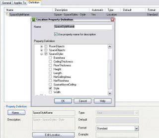
LocationCheckObjects Property Set Defintion and SpaceStyleName Location Property
The LocationCheckStyles Property Set Definition is set up to apply to all styles and definitions, although in the sample file I only used it on Multi-View Block Definitions. There are two properties, PermissionGranted and PermissionList. PermissionList is a text-type manual property that will hold a list of space style names into which a particular object has permission to be placed. A large, “executive” desk, for example, might include Office_Large in its list, but not Office_Small or any of the Workstation styles, as it would not be appropriate to place a desk of that size in a smaller space. The PermissionGranted formula property is where the heavy lifting is done. The VBScript InStr function is used to search the PermissionList manual property, starting at the first character [the first “1” in the parentheses after “InStr”], for an occurrence of the string in the LocationCheckObjects:SpaceStyleName property. The second “1” in the parentheses tells the InStr function to perform a text comparison, rather than a binary comparison. What that means is that the comparison will ignore the case of the text. For example, “a” matches “A” in a text comparison, but does not in a binary comparison. The InStr function returns an integer value under most circumstances – 0 if the string is not found or a positive integer indicating the starting character position in the target string of the first occurrence of the search string. So the formula tests the result to see if it is greater than zero. If so, then the space style name was found in the permission list and the object is permitted; if not, the name was not found [or there was no style name because the object was not placed over a space], and the object is not permitted. The image below shows the properties in the LocationCheckStyles Property Set Definition, as well as the PermissionGranted formula with sample data that returns a result of “YES”.
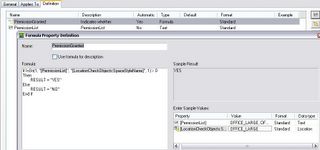
LocationCheckStyles Property Set Definition and PermissionGranted Formula Property
By attaching the SpaceStyles property set to each space style and attaching both the LocationCheckStyles property set to each object style or definition [filling in the PermissionList for each style/definition] and the LocationCheckObjects property set to each object, we can identify whether or not a particular object has been placed correctly. Looking at the Extended Data tab of the Properties Palette to find out whether PermissionGranted for each object is “YES” or “NO” would quickly become tedious. Checking a schedule table would be better, but unless you frequently remove objects from the schedule selection set, would quickly result in a schedule table that would be too big to keep close to the items being added. Display Themes to the rescue! Display Themes allow you to override the “normal” appearance that an object would have for the current Display Configuration and view direction, based on property data attached to the object. This should have great appeal for architects, who are, by and large, a visually oriented group.
Display Theme Style
The Display Theme in the sample file keys on the value in the PermissionGranted property. When the theme is applied, objects whose PermissionGranted value is “YES” will display in color 80 [a bright green]; color 10, a bright red, indicates a “NO” value. Objects that do not have the PermissionGranted property attached will continue to display as they do when the Display Theme is disabled.
Display Themes have styles, like other Architectural Desktop objects, and can be created and edited in the Style Manager, under the Documentation Objects category. In addition to the usual “General” tab, where you can edit the style name and description, Display Themes have three other tabs: Display Rules, where you define the display overrides – “Theme Settings” – and under which conditions each is to be applied – “Theme Rules”; Legend Format, where you set parameters for the Display Theme legend; and Legend Display Properties, where you control the visibility and display of the components of the components of the Display Theme legend.
Design Rules
The main work to be done is on the Design Rules tab. For this relatively simple example, there are two Theme settings, one for when PermissionGranted is “YES”, Index 1 in the image below, and one for when PermissionGranted is “NO”, Index 2.
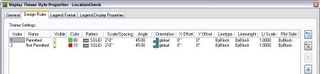
Theme Settings
The hatch parameters in a Theme Setting are only applied if the object has a hatch component turned on. Since Multi-View Blocks do not have a hatch component, the hatch settings have no effect in the sample file and I left them at the initial default values. Note also that I set up the sample Display Theme for on-screen purposes only. I left the Plot Style set to ByBlock, so unless the underlying object was set to plot using the object’s color, the sample file should plot the same whether or not the Display Theme was active. This appears to be the case using Plot Preview; I did not make any actual plots.
The Theme rules here are also quite simple. The LocationCheckStyles:PermissionGranted property holds the value to be shown graphically on the screen. Selecting Index 1 – “Permitted” – in the Theme Settings pane allows you to create Theme Rules for that index. Rule 1.1 states that Index 1 should be applied if the PermissionGranted property is equal to “YES”.

Theme Rules for Index 1 Theme Setting
Selecting Index 2 – “Not Permitted” – allows rules to be created for that index. Rule 2.1 states that Index 2 should be applied if the PermissionGranted property is equal to “NO”.

Theme Rules for Index 2 Theme Setting
Legend Format
Since “YES” and “NO” are the only two values that PermissionGranted can have, the Design Rules are complete. On the Legend Format tab, I set the Title to “Location Check” and the Text Style to “RomanS”, as shown below.
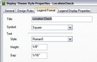
Legend Format
Legend Display Properties
I made no changes to the out-of-the-box settings in the sample file, as shown below.
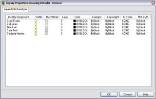
Legend Display Properties
Adding the Display Theme
I chose to add my display theme by setting up a tool, but you can also type _AecDisplayThemeAdd at the Command: prompt, then select the desired style in the Properties Palette. There does not appear to be a command-line option to select or enter the desired style name. A generic Display Theme tool can be found in the Scheduling and Reporting Tool category of the Stock Tool Catalog. i-drop this tool onto an editable tool palette, then edit its properties to reference the desired Display Theme style. For this sample file, I did not bother creating a source file for the style, but you would want to do so for any Display Themes you expect to reuse in other drawings. Have your tool reference the style in the source file by setting the Style location property, after saving the source file to a location that will be available to all who will use the tool.
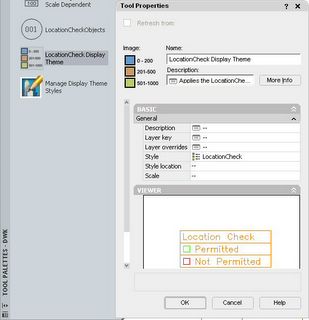
LocationCheck Display Theme Tool and Properties
When adding the Display Theme to a drawing, you will be prompted for the “Upper left corner of display theme:”. This is the upper left corner of the legend – pick an appropriate location. Similar to the prompts for a schedule table, you will then be asked to pick the “Lower right corner of display theme (or RETURN):”. If you pick a point, the legend will be scaled to fit between the two points; if you press ENTER or the space bar, the legend will be scaled according to the current drawing scale and annotation plot size as set in the Drawing Setup dialog. Assuming you have left all the display components turned on, the legend will show the title you entered on the Legend Format tab, along with a list of the Theme Settings accompanied by a square or circle showing the color and hatch pattern assigned to that setting. The Display Theme will also be applied to the current viewport. The legend in the sample file is shown below.
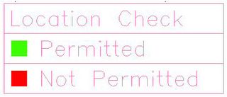
Display Theme Legend
By selecting the legend and right clicking, you have access to a context menu that gives access to editing commands specific to Display Themes. Of particular note is Disable Display Theme, which allows you to turn off the display theme without removing it from the drawing. If you select this, a diagonal slash will appear on the legend [if you leave that component turned on], the display changes set in the theme are deactivated, and the menu item changes to Apply Display Theme, which allows you to turn the theme back on.
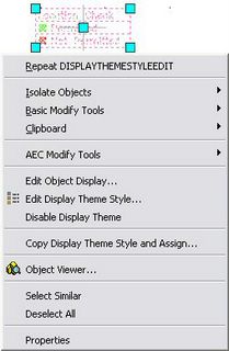
Display Theme Context Menu
The Results
By activating the Location Check Display Theme, you can get immediate feedback on whether a particular object is permitted in a space when moving or copying an existing object, and nearly immediate feedback when adding a new object that already has the LocationCheckStyles property set attached and PermissionList property completed – all you need do is add the LocationCheckObjects property set. The effect is most dramatic when working live in the file, so I would encourage you to download the sample file and try it out for yourself [if you have the 2006 release of Architectural Desktop – Display Themes do not work in prior versions]. Here are two screen shots of the men’s and women’s toilet rooms, each of which has a water closet, urinal and lavatory Multi-View Block. The first shows the out-of-the-box Medium Detail display, the second shows the effect of activating the LocationCheck Display Theme. The PermissionList property for the urinal does not include any of the women’s toilet room Space Style names, and so the instance of the block in the women’s room turns red, flagging it as “Not Permitted”. The other blocks turn green, indicating that they are permitted in the space in which they are placed.
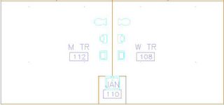
LocationCheck Display Theme Disabled
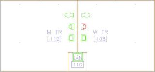
LocationCheck Display Theme Applied

Note that this is not meant to be a finished system, only a proof of concept. Using the space style name as the sole determinant may be too limiting in practice; setting up one or more manual properties in a style-based property set attached to the space style would allow you to have certain key words to identify space types without imposing burdens on the naming of the styles. The formula determining if an object is permitted could also be made more sophisticated, perhaps needing to match only part of the style name and/or splitting out the size [small, medium, large] comparison separately.
I found the sample file fascinating, but thought that in a file of “real project” size, that using a schedule table might be a little cumbersome. You would likely end up placing all of the objects, then generating the schedule and back-checking for items incorrectly placed. It occurred to me that having immediate, or near immediate feedback would improve the workflow. This seemed like just the excuse I needed to try out Display Themes, a feature added with the 2006 release.
I have posted a sample file of my own, in the Autodesk Architectural Desktop Customization Discussion Group. I chose to set up my sample file somewhat differently than the one noted above. Instead of listing all of the objects allowed in a space in the space style, I chose to list the space styles in which an object is permitted in the object’s style/definition. Either approach works – which is better for you depends upon your workflow and the number of different space styles and other objects that you would be including in your system.
Property Set Definitions
As always when dealing with schedule data, the first step is to establish the needed Property Set Definitions. I used style-based property sets – the out-of-the-box SpaceStyles Property Set Definition for the Style property and the custom LocationCheckStyles Property Set Definition – except for the location property that reads the style name from the space into the object’s property data. In Architectural Desktop 2006, the Location property could be part of the LocationCheckStyles Property Set Definition, but, for Multi-View Blocks anyway, the location grip is coincidental with the Multi-View Block insertion point grip, so it can not be moved independently of the block. I also found, when moving the Multi-View Block from room to room, that I had to use the ObjRelUpdate command to manually update the location property, so I chose to set up a separate, object-based Property Set Definition, LocationCheckObjects, to hold the location property. That does mean that you will need to attach the LocationCheckObjects property set to each object – you could set up a tool to do so, and apply it to multiple objects at once. As the goal is immediate feedback, this is not ideal, but I felt that having to attach the object-based property set once was less onerous than having to remember to run ObjRelUpdate every time a particular object was moved from one space to another. The way the formula is set up, the permission will show as “No” if the LocationCheckObjects property set is not attached, so having permission denied no matter where an object is placed should be a clue that the object-based property set is missing. Perhaps future versions of Architectural Desktop will improve the handling of style-based location properties. Remember, these did not work in style-based property sets at all in previous releases.
The LocationCheckObjects has one property, SpaceStyleName. This is a location property that reads in the name of the style of the space on which the object’s location grip is placed; the setting is shown in the image below.

LocationCheckObjects Property Set Defintion and SpaceStyleName Location Property
The LocationCheckStyles Property Set Definition is set up to apply to all styles and definitions, although in the sample file I only used it on Multi-View Block Definitions. There are two properties, PermissionGranted and PermissionList. PermissionList is a text-type manual property that will hold a list of space style names into which a particular object has permission to be placed. A large, “executive” desk, for example, might include Office_Large in its list, but not Office_Small or any of the Workstation styles, as it would not be appropriate to place a desk of that size in a smaller space. The PermissionGranted formula property is where the heavy lifting is done. The VBScript InStr function is used to search the PermissionList manual property, starting at the first character [the first “1” in the parentheses after “InStr”], for an occurrence of the string in the LocationCheckObjects:SpaceStyleName property. The second “1” in the parentheses tells the InStr function to perform a text comparison, rather than a binary comparison. What that means is that the comparison will ignore the case of the text. For example, “a” matches “A” in a text comparison, but does not in a binary comparison. The InStr function returns an integer value under most circumstances – 0 if the string is not found or a positive integer indicating the starting character position in the target string of the first occurrence of the search string. So the formula tests the result to see if it is greater than zero. If so, then the space style name was found in the permission list and the object is permitted; if not, the name was not found [or there was no style name because the object was not placed over a space], and the object is not permitted. The image below shows the properties in the LocationCheckStyles Property Set Definition, as well as the PermissionGranted formula with sample data that returns a result of “YES”.

LocationCheckStyles Property Set Definition and PermissionGranted Formula Property
By attaching the SpaceStyles property set to each space style and attaching both the LocationCheckStyles property set to each object style or definition [filling in the PermissionList for each style/definition] and the LocationCheckObjects property set to each object, we can identify whether or not a particular object has been placed correctly. Looking at the Extended Data tab of the Properties Palette to find out whether PermissionGranted for each object is “YES” or “NO” would quickly become tedious. Checking a schedule table would be better, but unless you frequently remove objects from the schedule selection set, would quickly result in a schedule table that would be too big to keep close to the items being added. Display Themes to the rescue! Display Themes allow you to override the “normal” appearance that an object would have for the current Display Configuration and view direction, based on property data attached to the object. This should have great appeal for architects, who are, by and large, a visually oriented group.
Display Theme Style
The Display Theme in the sample file keys on the value in the PermissionGranted property. When the theme is applied, objects whose PermissionGranted value is “YES” will display in color 80 [a bright green]; color 10, a bright red, indicates a “NO” value. Objects that do not have the PermissionGranted property attached will continue to display as they do when the Display Theme is disabled.
Display Themes have styles, like other Architectural Desktop objects, and can be created and edited in the Style Manager, under the Documentation Objects category. In addition to the usual “General” tab, where you can edit the style name and description, Display Themes have three other tabs: Display Rules, where you define the display overrides – “Theme Settings” – and under which conditions each is to be applied – “Theme Rules”; Legend Format, where you set parameters for the Display Theme legend; and Legend Display Properties, where you control the visibility and display of the components of the components of the Display Theme legend.
Design Rules
The main work to be done is on the Design Rules tab. For this relatively simple example, there are two Theme settings, one for when PermissionGranted is “YES”, Index 1 in the image below, and one for when PermissionGranted is “NO”, Index 2.

Theme Settings
The hatch parameters in a Theme Setting are only applied if the object has a hatch component turned on. Since Multi-View Blocks do not have a hatch component, the hatch settings have no effect in the sample file and I left them at the initial default values. Note also that I set up the sample Display Theme for on-screen purposes only. I left the Plot Style set to ByBlock, so unless the underlying object was set to plot using the object’s color, the sample file should plot the same whether or not the Display Theme was active. This appears to be the case using Plot Preview; I did not make any actual plots.
The Theme rules here are also quite simple. The LocationCheckStyles:PermissionGranted property holds the value to be shown graphically on the screen. Selecting Index 1 – “Permitted” – in the Theme Settings pane allows you to create Theme Rules for that index. Rule 1.1 states that Index 1 should be applied if the PermissionGranted property is equal to “YES”.

Theme Rules for Index 1 Theme Setting
Selecting Index 2 – “Not Permitted” – allows rules to be created for that index. Rule 2.1 states that Index 2 should be applied if the PermissionGranted property is equal to “NO”.

Theme Rules for Index 2 Theme Setting
Legend Format
Since “YES” and “NO” are the only two values that PermissionGranted can have, the Design Rules are complete. On the Legend Format tab, I set the Title to “Location Check” and the Text Style to “RomanS”, as shown below.

Legend Format
Legend Display Properties
I made no changes to the out-of-the-box settings in the sample file, as shown below.
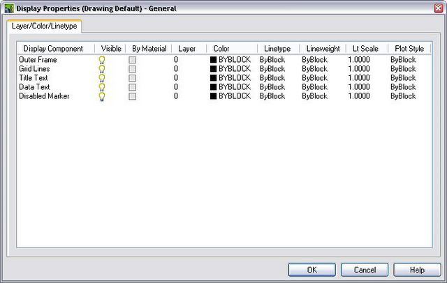
Legend Display Properties
Adding the Display Theme
I chose to add my display theme by setting up a tool, but you can also type _AecDisplayThemeAdd at the Command: prompt, then select the desired style in the Properties Palette. There does not appear to be a command-line option to select or enter the desired style name. A generic Display Theme tool can be found in the Scheduling and Reporting Tool category of the Stock Tool Catalog. i-drop this tool onto an editable tool palette, then edit its properties to reference the desired Display Theme style. For this sample file, I did not bother creating a source file for the style, but you would want to do so for any Display Themes you expect to reuse in other drawings. Have your tool reference the style in the source file by setting the Style location property, after saving the source file to a location that will be available to all who will use the tool.

LocationCheck Display Theme Tool and Properties
When adding the Display Theme to a drawing, you will be prompted for the “Upper left corner of display theme:”. This is the upper left corner of the legend – pick an appropriate location. Similar to the prompts for a schedule table, you will then be asked to pick the “Lower right corner of display theme (or RETURN):”. If you pick a point, the legend will be scaled to fit between the two points; if you press ENTER or the space bar, the legend will be scaled according to the current drawing scale and annotation plot size as set in the Drawing Setup dialog. Assuming you have left all the display components turned on, the legend will show the title you entered on the Legend Format tab, along with a list of the Theme Settings accompanied by a square or circle showing the color and hatch pattern assigned to that setting. The Display Theme will also be applied to the current viewport. The legend in the sample file is shown below.

Display Theme Legend
By selecting the legend and right clicking, you have access to a context menu that gives access to editing commands specific to Display Themes. Of particular note is Disable Display Theme, which allows you to turn off the display theme without removing it from the drawing. If you select this, a diagonal slash will appear on the legend [if you leave that component turned on], the display changes set in the theme are deactivated, and the menu item changes to Apply Display Theme, which allows you to turn the theme back on.
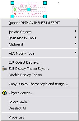
Display Theme Context Menu
The Results
By activating the Location Check Display Theme, you can get immediate feedback on whether a particular object is permitted in a space when moving or copying an existing object, and nearly immediate feedback when adding a new object that already has the LocationCheckStyles property set attached and PermissionList property completed – all you need do is add the LocationCheckObjects property set. The effect is most dramatic when working live in the file, so I would encourage you to download the sample file and try it out for yourself [if you have the 2006 release of Architectural Desktop – Display Themes do not work in prior versions]. Here are two screen shots of the men’s and women’s toilet rooms, each of which has a water closet, urinal and lavatory Multi-View Block. The first shows the out-of-the-box Medium Detail display, the second shows the effect of activating the LocationCheck Display Theme. The PermissionList property for the urinal does not include any of the women’s toilet room Space Style names, and so the instance of the block in the women’s room turns red, flagging it as “Not Permitted”. The other blocks turn green, indicating that they are permitted in the space in which they are placed.
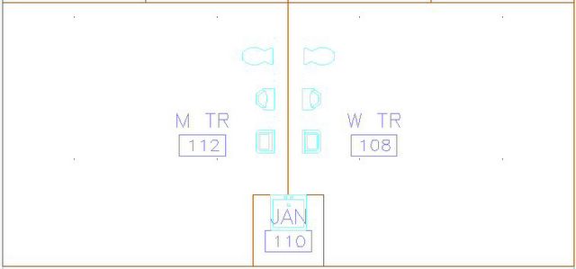
LocationCheck Display Theme Disabled
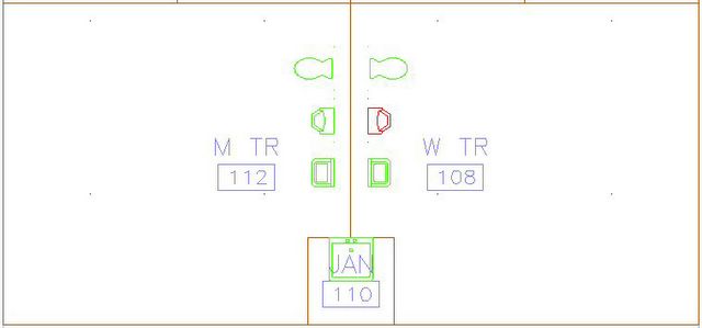
LocationCheck Display Theme Applied
Note that this is not meant to be a finished system, only a proof of concept. Using the space style name as the sole determinant may be too limiting in practice; setting up one or more manual properties in a style-based property set attached to the space style would allow you to have certain key words to identify space types without imposing burdens on the naming of the styles. The formula determining if an object is permitted could also be made more sophisticated, perhaps needing to match only part of the style name and/or splitting out the size [small, medium, large] comparison separately.
October 04, 2005
Richard Binning on Copying Layer Keys Between Styles
Richard Binning has posted the follow up to his July 29, 2005 blog post on copying Layer Keys between two Layer Key Styles. That first post provides a downloadable Excel tool to make comparing two Layer Key Styles easier; the new post (October 3, 2005) includes a VBA routine that allows you to copy Layer Keys between Layer Key Styles. Check out both posts in "beside the cursor...". And thanks to Richard for providing such a useful tool to those of us who VBA challenged.
Triple D Design Wiki
Beau Turner has unveiled the Triple D Design Wiki, a resource to allow the architectural/engineering community to share their experience using 3D Design software. You can read more about this in his blog, or jump right into the Triple D Design Wiki.
Phase I provides an area for Architectural Desktop users to pool their knowledge. A future Phase II is planned, to suppport Revit Building users.
Here is another opportunity to tap into the accumulated knowledge of the ADT user community, as well as to contribute to it. If you have mastered some part of ADT, share that hard-earned knowledge with others, and learn something new from someone else.
Phase I provides an area for Architectural Desktop users to pool their knowledge. A future Phase II is planned, to suppport Revit Building users.
Here is another opportunity to tap into the accumulated knowledge of the ADT user community, as well as to contribute to it. If you have mastered some part of ADT, share that hard-earned knowledge with others, and learn something new from someone else.
September 24, 2005
Scale-dependent Tag Tools in ADT 2006
The out-of-the-box scale-dependent room tag tools, provided in the Documentation Tool Catalog - Imperial and - Metric, use the new tag tools, just like their single-scale bretheren. Unfortunately, there is no way in the tag tool to specify a scaling type - all tags using the tag tool have annotation scaling applied. For single-scale tags, that would be my preference, but the scale-dependent tags are designed to be inserted at scale factor of 1; the view blocks inside are already pre-scaled for three differenent scales: 1/16" = 1'-0", 1/8" = 1'-0" and 1/4" = 1'-0" for the imperial tag and 1:200, 1:100 and 1:50 for the metric tag. Applying annotation scaling to these tags causes them to be inserted incorrectly under most drawing scale/annotation plot size combinations, including those likely to be used.
I can think of two work-arounds, neither totally ideal, but if scale-dependent tags are important to your workflow, you may need to decide which is the better way to work for you.
Keeping the Out-of-the-box Content and Tool
You can get the out-of-the-box tool to insert the tag at the necessary scale factor of one by setting your drawing scale to be the inverse of your annotation plot size, while placing tags. For example, if you are in an imperial drawing and have 3/32" as your annotation plot size, you can set your scale to a custom scale of 32/3 [10.666666666666666...]. Do this by calling up the Drawing Setup dialog, selecting the Scale tab and choosing Other... from the Scale list. This makes the Custom Scales edit box active - type 32/3 in the edit box and select OK to return to the drawing. Place your scale-dependent tags, then remember to reset the scale to an appropriate value for any subsequent editing. You can also set your annotation plot size to the inverse of your drawing scale. So if your drawing scale is 1/8" = 1'-0", set your annotation plot size to 1/96. Working out the inverses is, of course, much easier for metric users.
Creating an AEC Content File and Tool
The other option is to set up an AEC Content file using the Create AEC Content Wizard and the _AecAnnoScheduleTagAdd custom command, just like all tags were done in previous versions of ADT. On the "second" page of the Wizard, you will want to choose the None radio button under additional scaling [and set the X, Y and Z scale factors to 1, unless your Multi-View Block requires some other scaling factors to work properly]. As in prior versions, you will need to put your finished AEC Content file somewhere under the root folder specified for AEC DesignCenter Content on the AEC Content tab of the Options dialog. You will also need to create a file to hold the Property Set Definitions required by your tag, place that file in the same folder as the tag or one folder above the tag and specify that file as the source file in the _AecAnnoScheduleTagAdd command string. In previous versions, this source file was called PropertySetDefs.dwg, but you can call the file by any name you like, as long as you get the name right in the command string. This is my preferred method of handling scale-dependent tags, but I am bothered by the need to have Property Set Definitions defined in two places - the source file for all of the other tags and the "PropertySetDefs.dwg" needed for the scale-dependent tags.
You can read more about scale-dependent tags here.
Here is hoping that a future version of ADT will allow the user to specify a scaling type in the tool, so that all tags can be kept in the same source file.
1/20/2007 Update: See this post for a way to set up scale-dependent tags without setting special combinations of drawing scale/annotation plot size, needing two source files for Property Set Definitions or "breaking" existing tools by moving the out-of-the-box scheduling source file.
I can think of two work-arounds, neither totally ideal, but if scale-dependent tags are important to your workflow, you may need to decide which is the better way to work for you.
Keeping the Out-of-the-box Content and Tool
You can get the out-of-the-box tool to insert the tag at the necessary scale factor of one by setting your drawing scale to be the inverse of your annotation plot size, while placing tags. For example, if you are in an imperial drawing and have 3/32" as your annotation plot size, you can set your scale to a custom scale of 32/3 [10.666666666666666...]. Do this by calling up the Drawing Setup dialog, selecting the Scale tab and choosing Other... from the Scale list. This makes the Custom Scales edit box active - type 32/3 in the edit box and select OK to return to the drawing. Place your scale-dependent tags, then remember to reset the scale to an appropriate value for any subsequent editing. You can also set your annotation plot size to the inverse of your drawing scale. So if your drawing scale is 1/8" = 1'-0", set your annotation plot size to 1/96. Working out the inverses is, of course, much easier for metric users.
Creating an AEC Content File and Tool
The other option is to set up an AEC Content file using the Create AEC Content Wizard and the _AecAnnoScheduleTagAdd custom command, just like all tags were done in previous versions of ADT. On the "second" page of the Wizard, you will want to choose the None radio button under additional scaling [and set the X, Y and Z scale factors to 1, unless your Multi-View Block requires some other scaling factors to work properly]. As in prior versions, you will need to put your finished AEC Content file somewhere under the root folder specified for AEC DesignCenter Content on the AEC Content tab of the Options dialog. You will also need to create a file to hold the Property Set Definitions required by your tag, place that file in the same folder as the tag or one folder above the tag and specify that file as the source file in the _AecAnnoScheduleTagAdd command string. In previous versions, this source file was called PropertySetDefs.dwg, but you can call the file by any name you like, as long as you get the name right in the command string. This is my preferred method of handling scale-dependent tags, but I am bothered by the need to have Property Set Definitions defined in two places - the source file for all of the other tags and the "PropertySetDefs.dwg" needed for the scale-dependent tags.
You can read more about scale-dependent tags here.
Here is hoping that a future version of ADT will allow the user to specify a scaling type in the tool, so that all tags can be kept in the same source file.
1/20/2007 Update: See this post for a way to set up scale-dependent tags without setting special combinations of drawing scale/annotation plot size, needing two source files for Property Set Definitions or "breaking" existing tools by moving the out-of-the-box scheduling source file.
September 19, 2005
ADT 2006 Service Pack 1 Available
Service Pack 1 for ADT 2006 is now available from the Autodesk website. As always, read the Readme before installing the Service Pack.
September 17, 2005
Replace Z Value and Copy Definition and Assign Rock
I spent some time today taking a drawing from a furniture vendor where the layout was done with their own 3D/2D blocks and converting it to a simpler, 2D only layout for use as an overlay Xref in our plans. The annoyance of working at home on a weekend was partially offset by the pleasure of being able to turn on the Replace Z Value feature in ADT 2006 and know that no matter what part of the vendor's layout I snapped to while creating my simplified version, my linework would remain a Z=0.
This was an update to a previous plan, so I already had some graphics, including blocks for some of the repeated items. I was pleased to find that the Copy Definition and Assign feature, which I knew worked on ADT style-based objects, also worked on AutoCAD blocks. I had a typical office desk block set up, and there were a few that, were similar, but one worksurface was larger. I was able to place the block I had, select that instance, right click and select the Copy Block Definition and Assign from the context menu. A dialog appeared asking for a name for the new block, offereing the old name with " (2)" appended. After editing the name and clicking OK, all I had to do was REFEDIT the new block instance, stretch the worksurface and save the changes and I was done. No need to remember where the insertion point was or worry if the instance was mirrored and/or rotated. No messy explosion and reblocking under a new name.
Sometimes it is the seemingly smallest improvements which provide the greatest pleasure, particularly if they ease frequently encountered procedures or address a long-standing source of frustration.
This was an update to a previous plan, so I already had some graphics, including blocks for some of the repeated items. I was pleased to find that the Copy Definition and Assign feature, which I knew worked on ADT style-based objects, also worked on AutoCAD blocks. I had a typical office desk block set up, and there were a few that, were similar, but one worksurface was larger. I was able to place the block I had, select that instance, right click and select the Copy Block Definition and Assign from the context menu. A dialog appeared asking for a name for the new block, offereing the old name with " (2)" appended. After editing the name and clicking OK, all I had to do was REFEDIT the new block instance, stretch the worksurface and save the changes and I was done. No need to remember where the insertion point was or worry if the instance was mirrored and/or rotated. No messy explosion and reblocking under a new name.
Sometimes it is the seemingly smallest improvements which provide the greatest pleasure, particularly if they ease frequently encountered procedures or address a long-standing source of frustration.
September 15, 2005
Rounding to Death
I have had a chance to test my latest file in ADT 2004. When using a Property Data Format to perform rounding, the Up and Down options work as expected when the Round Off Value is set to any of the values I tested, other than 0. That advice applies to 2004, 2005 and 2006.
When using the Nearest option, the results for 2004 are different than for 20054 and 2006. In 2004, the Nearest option appears to work correctly only when the Round Off value is set to 0. You can then set the Precision value and the rounding will take place at the last digit. This limits the Nearest option to rounding to the nearest integer, tenth, hundredth, thousandth...or hundred millionth. If you need to round to the nearest five, nearest 100 or nearest half, you will need to use a formula property or upgrade to 2005 or 2006. For other Round Off Values, positive numbers are always rounded down and negative numbers are always rounded up [closer to zero in both cases].
I also found that there were some numbers that did not round correctly even though the method appears to work reliably for all of the other cases tested. Obviously, I did not test every possible number, so this is not an exhaustive listing, but would be good to keep in mind if you use rounding for critical data.
2.0075, when the Round Off Value is 0.001, rounded nearest incorrectly for both the PDF method and my formula. That was the only tested number in which my formula failed. Perhaps there is some issue with how that number is represented in binary that causes the incorrect rounding. [Note that 7.5, with a Round Off Value of 1, works just fine for both methods, so it does not always happen when rounding a "7" and the next digit is "5".]
-2.0075 and -2.0025 both rounded incorrectly when using the PDF method with Round Off Value set to 0 and the Precision set to 0.001.
When using the Nearest option, the results for 2004 are different than for 20054 and 2006. In 2004, the Nearest option appears to work correctly only when the Round Off value is set to 0. You can then set the Precision value and the rounding will take place at the last digit. This limits the Nearest option to rounding to the nearest integer, tenth, hundredth, thousandth...or hundred millionth. If you need to round to the nearest five, nearest 100 or nearest half, you will need to use a formula property or upgrade to 2005 or 2006. For other Round Off Values, positive numbers are always rounded down and negative numbers are always rounded up [closer to zero in both cases].
I also found that there were some numbers that did not round correctly even though the method appears to work reliably for all of the other cases tested. Obviously, I did not test every possible number, so this is not an exhaustive listing, but would be good to keep in mind if you use rounding for critical data.
2.0075, when the Round Off Value is 0.001, rounded nearest incorrectly for both the PDF method and my formula. That was the only tested number in which my formula failed. Perhaps there is some issue with how that number is represented in binary that causes the incorrect rounding. [Note that 7.5, with a Round Off Value of 1, works just fine for both methods, so it does not always happen when rounding a "7" and the next digit is "5".]
-2.0075 and -2.0025 both rounded incorrectly when using the PDF method with Round Off Value set to 0 and the Precision set to 0.001.
September 03, 2005
Rounding Redux
UPDATE, 9/10/2005: Jon Smith of Construction Industry Solutions (COINS) has pointed out that the problem with the rounding using Property Data Formats in my sample file was that I had the Round Value set to "0"; the problem disappears if you use "1" instead. I have confirmed that this is true for ADT 2006 and ADT 2005. I will post back with results in ADT 2004 when I get a chance to try my new test file at work next week. In the mean time, the new test file is available from the same thread in the Autodesk Architectural Desktop Content Discussion Group to which I posted the previous test file.
A third, and, to the relief of those who could not care less about rounding, what I hope to be final post on rounding numerical property data in Autodesk Architectural Desktop 2004, 2005 or 2006. I have taken the test drawing I did in ADT 2004 [see this blog post for more information], brought it into ADT 2006 [so I could take advantage of the enhanced editor - the file should still open and work in ADT 2004] and made some changes. I renamed the properties that tested property data formats to try to achieve rounding, adding "PDF" to their names for easy identification. Since these do not work in the current verisons, you will not want to be copying them. I thought about removing them, but decided that I would leave them in so I would have one file for use in testing future releases. I deleted the formula that used the VBScript Round function to round "nearest" to two decimal places and replaced it with three generic rounding formulas which could be used as a starting point for setting up rounding in an actual application. I added a manual property called TableOrder, so I could control the sorting of the schedule table and keep each line object next to its schedule table row. I have posted a ZIP file that includes a sample file, to the Autodesk Architectural Desktop Content Discussion group, for anyone who would like to download a working example of what is discussed below.
In order to provide flexibility and to match the rounding functionality present in Property Data Formats, I added a new, real number manual property, RoundValue. This provides the equivalent of the Round Off Value in the Property Data Formats. The default value is 1, which rounds to the nearest whole number. To round to two decimal places, enter 0.01. To round to one half, enter 0.5. To round to the nearest 100, enter 100. The math behind the function involves division, so entering 0 would cause an undefined value. The formulas convert an entered value of 0 to 1.
There are three new formulas - one to round up, one to round down and one to round to nearest. I considered setting up nearest to work like the VBScript function, where exactly 5 in the digit beyond the rounding digit would round up for odd numbers in the rounding digit and down for even numbers in the rounding digit. While that may make some sense when the RoundValue is 1 times 10 to some power, for RoundValues like 50, where 275 would round up to 300 but 225 would round down to 200, the "oddness" or "eveness" of the starting number was not readily apparent. I chose to take the easy way out and simply have exactly 5 always round up. The properties in my revised LineObjects Property Set Definition are shown below.
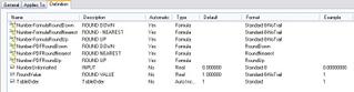
The new formulas also work with negative numbers, should your application require that. I chose to treat negative numbers such that rounding up goes to a higher number and down goes to a smaller number. For example, -10.5 would be rounded up to -10 and down to -11. I changed the function I used for rounding from Fix, used in the previous rounding formulas, to Int, as that handles negative numbers in the way previously described. [For negative numbers, Fix rounds up away from zero and down towards zero; in other words, it rounds up to the greater absolute value. Fix and Int return the same results for positive numbers.]
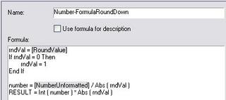
The Number-FormulaRoundDown formula property is the simplest. After converting any zero value in RoundValue to 1, the formula divides the source number by the absolute value of RoundValue, uses the Int function to truncate any decimal portion, then multiplies that whole number portion by the absolute value of RoundValue to arrive at the desired result. The formula, as it appears in ADT 2006, is shown below.
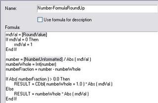
The Number-FormulaRoundUp formula property works in a similar fashion, dividing by the RoundValue, truncating any fraction and multiplying that by the RoundValue, but needs to determine if there is any fractional part that would require rounding up. This is done by storing intermediate results in variables, calculating the fractional part and, if any, adding one to the whole number before finally multiplying it by the absolute value of RoundValue to get the final result. The formula is shown below.
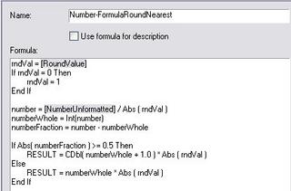
The Number-FormulaRoundNearest formula property is almost identical to the round up property, except that adding one to the whole number value only happens if the fractional part is 0.5 or greater. The formula is shown below.
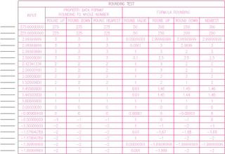
There is a schedule table in the sample file that shows the results of various sample values and, for the formulas, various RoundValues. As before, lines are used as the objects to hold the properties. As previously noted the table is sorted by the vaule in TableOrder; the TableOrder column is hidden in the Schedule Table Style. Feel free to play around with the values assigned to any line to see how the results of the different rounding formulas change.
You should be able to adapt one of these formulas to accomplish any property data rounding needs you may have, until such time as the rounding feature in the Property Data Formats is corrected. When you substitute the property you wish to round for the NumberUnformatted property in the sample file, make certain that you have a number and not a string. Read more about creating unformatted numeric properties in my previous blog article on that subject. Also note that if, for a given formula, the rounding value will always be the same, you do not need to have the RoundValue property, and can enter the number directly in the formula, by replacing each instance of "Abs ( rndVal )" with your desired value [use a positive value]. In that case, you can delete the first five lines, which read in the value of RoundValue and substitute 1 if the value is 0.
A third, and, to the relief of those who could not care less about rounding, what I hope to be final post on rounding numerical property data in Autodesk Architectural Desktop 2004, 2005 or 2006. I have taken the test drawing I did in ADT 2004 [see this blog post for more information], brought it into ADT 2006 [so I could take advantage of the enhanced editor - the file should still open and work in ADT 2004] and made some changes. I renamed the properties that tested property data formats to try to achieve rounding, adding "PDF" to their names for easy identification. Since these do not work in the current verisons, you will not want to be copying them. I thought about removing them, but decided that I would leave them in so I would have one file for use in testing future releases. I deleted the formula that used the VBScript Round function to round "nearest" to two decimal places and replaced it with three generic rounding formulas which could be used as a starting point for setting up rounding in an actual application. I added a manual property called TableOrder, so I could control the sorting of the schedule table and keep each line object next to its schedule table row. I have posted a ZIP file that includes a sample file, to the Autodesk Architectural Desktop Content Discussion group, for anyone who would like to download a working example of what is discussed below.
In order to provide flexibility and to match the rounding functionality present in Property Data Formats, I added a new, real number manual property, RoundValue. This provides the equivalent of the Round Off Value in the Property Data Formats. The default value is 1, which rounds to the nearest whole number. To round to two decimal places, enter 0.01. To round to one half, enter 0.5. To round to the nearest 100, enter 100. The math behind the function involves division, so entering 0 would cause an undefined value. The formulas convert an entered value of 0 to 1.
There are three new formulas - one to round up, one to round down and one to round to nearest. I considered setting up nearest to work like the VBScript function, where exactly 5 in the digit beyond the rounding digit would round up for odd numbers in the rounding digit and down for even numbers in the rounding digit. While that may make some sense when the RoundValue is 1 times 10 to some power, for RoundValues like 50, where 275 would round up to 300 but 225 would round down to 200, the "oddness" or "eveness" of the starting number was not readily apparent. I chose to take the easy way out and simply have exactly 5 always round up. The properties in my revised LineObjects Property Set Definition are shown below.

LineObjects Property Set Definition
The new formulas also work with negative numbers, should your application require that. I chose to treat negative numbers such that rounding up goes to a higher number and down goes to a smaller number. For example, -10.5 would be rounded up to -10 and down to -11. I changed the function I used for rounding from Fix, used in the previous rounding formulas, to Int, as that handles negative numbers in the way previously described. [For negative numbers, Fix rounds up away from zero and down towards zero; in other words, it rounds up to the greater absolute value. Fix and Int return the same results for positive numbers.]
The Number-FormulaRoundDown formula property is the simplest. After converting any zero value in RoundValue to 1, the formula divides the source number by the absolute value of RoundValue, uses the Int function to truncate any decimal portion, then multiplies that whole number portion by the absolute value of RoundValue to arrive at the desired result. The formula, as it appears in ADT 2006, is shown below.

Number-FormulaRoundDown Formula
The Number-FormulaRoundUp formula property works in a similar fashion, dividing by the RoundValue, truncating any fraction and multiplying that by the RoundValue, but needs to determine if there is any fractional part that would require rounding up. This is done by storing intermediate results in variables, calculating the fractional part and, if any, adding one to the whole number before finally multiplying it by the absolute value of RoundValue to get the final result. The formula is shown below.
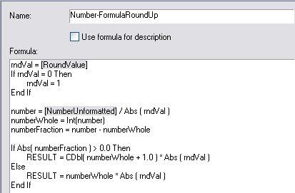
Number-FormulaRoundUp Formula
The Number-FormulaRoundNearest formula property is almost identical to the round up property, except that adding one to the whole number value only happens if the fractional part is 0.5 or greater. The formula is shown below.
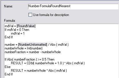
Number-FormulaRoundNearest Formula
There is a schedule table in the sample file that shows the results of various sample values and, for the formulas, various RoundValues. As before, lines are used as the objects to hold the properties. As previously noted the table is sorted by the vaule in TableOrder; the TableOrder column is hidden in the Schedule Table Style. Feel free to play around with the values assigned to any line to see how the results of the different rounding formulas change.

Rounding Test Schedule Table
You should be able to adapt one of these formulas to accomplish any property data rounding needs you may have, until such time as the rounding feature in the Property Data Formats is corrected. When you substitute the property you wish to round for the NumberUnformatted property in the sample file, make certain that you have a number and not a string. Read more about creating unformatted numeric properties in my previous blog article on that subject. Also note that if, for a given formula, the rounding value will always be the same, you do not need to have the RoundValue property, and can enter the number directly in the formula, by replacing each instance of "Abs ( rndVal )" with your desired value [use a positive value]. In that case, you can delete the first five lines, which read in the value of RoundValue and substitute 1 if the value is 0.
Subscribe to:
Posts (Atom)