First post in the series: ACA Ceiling Grids: The Cell Component
Previous post in the series: ACA Ceiling Grids: Mask Blocks
As seen in the previous article, Mask Blocks provide a great way to hide unwanted parts of a Ceiling Grid when an item to be placed in the ceiling is larger than one grid cell. The out-of-the-box content contains several light fixtures as part of a Mask Block, but you may need to create your own, to match your office standard graphics.
Mask Blocks have two parts, one required and one optional. The required part is one or more closed 2D polylines, splines, ellipses, or circles, to define the area to be masked. The closed polylines have to be the "newer," optimized LWPolyline type. A single object will define the area to be masked. If more than one object, or "ring" is selected, they must lie completely within or outside of each other; the rings cannot cross or touch each other. The first object will be define a mask area; you will be prompted to indicate whether subsequent rings are "void areas", or holes in the mask area, or an additional mask area.
The second, optional part is additional graphics. If you use the out-of-the-box display settings, the ring(s) selected in for the first part get placed on a non-plot layer; the additional graphics provide the plotable graphics of the Mask Block. The out-of-the-box luminaires that would span two square tiles (2'-0" or 450 mm square) are Mask Blocks with a Multi-View Block for the additional graphics. For the out-of-the-box General and Reflected Display Representations of Mask Blocks, the additional graphics end up on Layer 0, with ByBlock attributes. As these are nested within the Mask Block object, they end up inheriting the properties of the layer on which the Mask Block is placed.
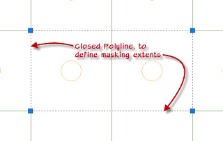
The first step in creating a Mask Block is to draw the closed 2D polyline(s), spline(s), ellipse(s), and/or circle(s) that will define the mask. As previously noted, these items will define a component that is on a non-plotting layer if you are using the out-of-the-box Display Representations.The mask created will stop short of masking any AEC object linework that is directly under the defining linework, so to mask a 2'-0" square Ceiling Grid for a 4'-0" x 2'-0" object, you can draw the defining closed polyline rectangle with opposite sides of 4'-0" and 2'-0". When aligned with a Ceiling Grid, the crossing grid will be masked, but the perimeter grids will still display.
The next step is to create the additional graphics. For this example, I created a Multi-View Block with the plan graphics for a 4'-0" x 2'-0" supply diffuser. Place an instance of the additional graphics in the proper location, relative to the mask definition object(s).If you want the additional graphics to pick up the layer, color, linetype, lineweight and plotstyle of the parent Mask Block, then the object(s) for the additional graphics should be on Layer 0, with color, linetype, lineweight and plotstyle set to ByBlock. If your additional graphics include an AutoCAD block or an ACA Multi-View Block, then the objects in the block definition or view block definition should also be on Layer 0 with ByBlock attributes. To set the attributes of an ACA object (such as a Multi-View Block), select the object, right click and choose Edit Object Display from the context menu, and choose the General Properties tab, since these properties are not exposed for ACA objects on the Design tab of the Properties palette.Finally, open the Style Manager (on the Manage ribbon tab, on the Style & Display panel, choose the Style Manager tool), expand the Multi-Purpose Objects node and select the Mask Block Definitions node. In the right pane, right click on an empty area and choose New from the context menu. Give the new Mask Block Definition a name and, optionally, a description. Right click on the new name and choose Set From... on the context menu.The Style Manager will close, and the Command Line will display prompts to guide you through the process. The first prompt asks you to "Select a closed polyline, spline, ellipse or circle". Select one of your "rings" that define a masking area; in the example, the 4'-0" x 2'-0" rectangle. The next prompt asks if you want to "Add another ring?". If you only have one defining object, answer "No". If you have additional rings to add, answer "Yes", select another, indicate if it should be a void area and then indicate if you have another ring to select. Once you say "No" to adding another ring, you will be prompted for the "Insertion base point". Choose a point in the drawing to serve as the insertion point for the Mask Block. In the example, I set the lower left corner (grid node) as the insertion point. In response to the "Select additional graphics" prompt, select the additional graphics (if any) to be included in the Mask Block. Press the Enter key when you are done selecting additional graphics, and the Style Manager will reopen. Select OK to dismiss the Style Manager and your Mask Block Definition is ready to be used. Erase your ring(s) and additional graphics if you have no other use for them.
You can now use the MASKADD command to add an instance of the newly created Mask Block Definition and attach it to a Ceiling Grid.


No comments:
Post a Comment