
But perhaps you have a need for a structural member style that is not in the catalog, whether to use it as a “generic” member, until the actual member is determined and you prefer not to use a real-world shape to make it easy to distinguish later; you have a special size not in the catalog; or you have some other need for a shape not in the catalog. For example, a while back, Brad Crouse had posted in the AUGI Forums [see this thread and this thread] that he was trying to create model in ADT at 1/16 actual size, in order to show, at full size, the “toy” buildings he intends to build.
One option would be to create custom structural member shapes, by drawing each outline as a closed polyline, and then using the -AecsMemberShape command to create the shapes. But if the shapes you need match “standard” structural shapes, with non-statndard size parameters, you may be able to save yourself some time and effort by using the Structural Member Wizard. You can access the Wizard from the pulldown menus, Format > Structural Members > Wizard…, or by invoking the _AecsMemberStyleWizard command.
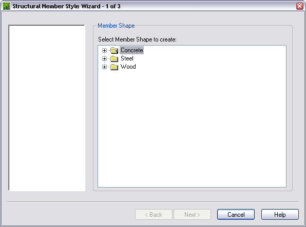
The Structural Member Wizard is a handy, dialog-driven utility that prompts you for the appropriate dimensional parameters for various types of concrete, steel or wood shapes, then generates a Structural Member Shape and Style for you to use. You can see the available options in the images below for concrete…

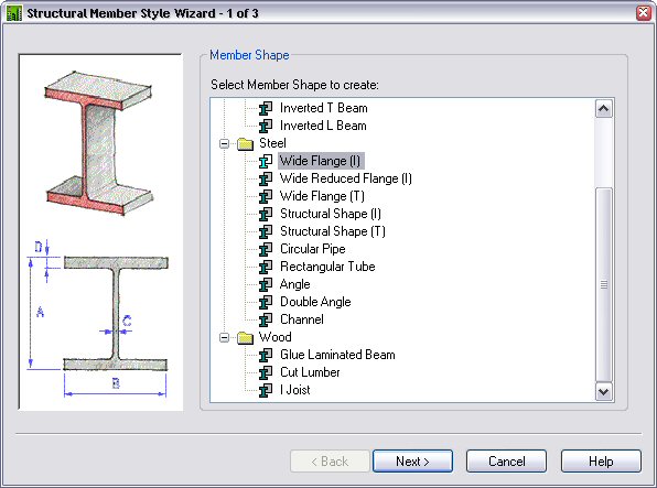
…steel…

…and wood.

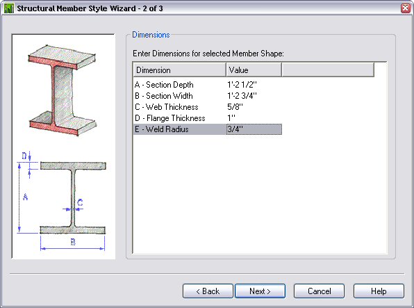
Let’s assume that our project is in the Schematic Design Phase, and we have managed to get the structural engineers to commit to using W14’s for the columns. We do not know the exact size for any of the columns, but the engineers have allowed that the largest column would be a W14x99. For schematic purposes, we want to make certain that our column enclosures can handle both the widest and deepest section, so we will use the Structural Member Wizard to create a “composite” structural member that combines the flange width of the W14x99, 14.656”, with the depth of the the W14x82, 14.31”, rounded up in case the final calculations sneak in a larger member or two. Our schematic column will have the following parameters:
A – Depth: 14.5
B – Flange Width: 14.75
C – Web Thickness: 0.625
D – Flange Thickness: 1.00
E – Weld Radius: 0.75
Start up the Structural Member Wizard and choose the Steel Wide Flange (I) option on “page” 1 of 3.
Select Next > to move to page 2 of 3, and enter the data noted above.
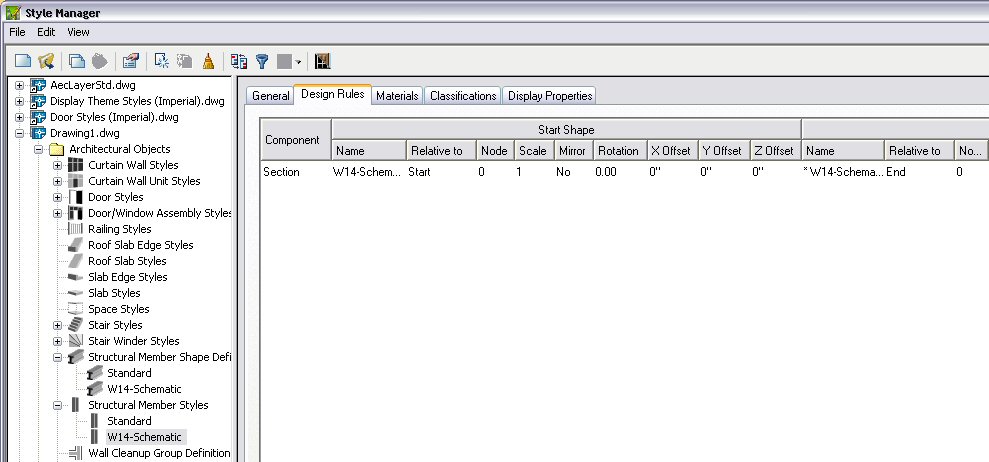
Select Next > and enter a style name, like “W14-Schematic” on page 3 of 3, then select Finish.

The Wizard then creates both a Structural Member Shape Definition and a Structural Member Style called “W14-Schematic”, ready for you to use.
1 comment:
THANK YOU FOR THIS ARTICLE!
LYNN @ DFWCGI
Post a Comment