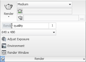
The Render tab is the fourth static (always available) tab provided in the out-of-the-box ACA CUI. The image below and all screen captures in this article are based on the shipping version.

Tools Panel
The Tools Panel contains a single button that toggles the tool palettes on and off, setting the Visualization tool palette group current when toggling it back on.
 If you would prefer that it simply switch to the Visualization tool palette group, refer to this previous article for instructions on how to modify the CUIX file.
Render Panel
The Render Panel contains commands related to rendering.
 The Render split button split button allows you to render or render a region.
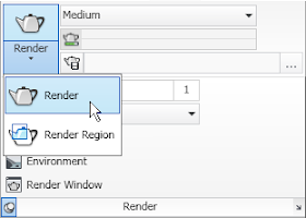 The main button will change to run the most recently chosen option from the drop-down list. The Render Presets drop-down button offers a list of named, pre-established rendering settings. The most recently used choice is displayed when the drop-down list is collapsed.
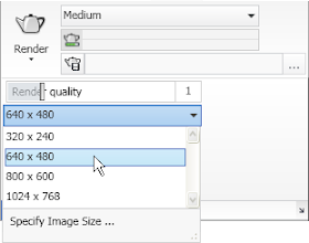
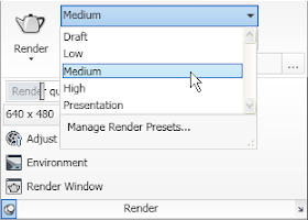 Choose Manage Render Presets at the bottom of the drop-down list to open the Render Presets Manager dialog, where you can edit the current settings, review the settings assigned to any of the standard presets as well as create or edit custom render presets (RENDERPRESETS command). The button below the Render Presets drop-down does not execute a command, but shows a histogram indicating the progress of a rendering in progress. Selecting the button at the left side of the third row on the main panel, Render Output File, toggles whether or not a rendered image is saved to a file. When enabled (bluish background, rather than gray), the Browse for File button at the right side of that same row (elipsis icon) becomes enabled, allowing you to specify the path and file name for the rendering file. The text box in the middle of the third row will display the path and name of the specified file. Select the Render panel title bar to expand the panel. A slider button shows the current render quality. The Render Output Size drop-down offers four standard image sizes; choose Specify Image Size at the bottom to open the Output Size dialog, where you can set a custom size for the rendered image.
 The Adjust Exposure button (RENDEREXPOSURE command) opens the Adjust Rendered Exposure dialog when the LIGHTINGUNITS system variable is not set to 0. The Environment button opens the Render Environment dialog, where you can enable or disable "Fog" and control various parameters thereof (RENDERENVIRONMENT). The Render Window button (RENDERWIN) opens the Render window without starting a rendering operation, allowing you to view previously rendered images for drawings with a "render history." The open arrow pointing to the lower right icon, at the far right side of the Render panel title bar, will toggle the Advanced Render Settings palette on and off.
Materials Panel
The Materials Panel contains commands related to render materials.
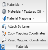 The Materials split button allows you to toggle the open/close state of the Materials palette (MATERIALS command) or to set the mapping of materials on selected object(s) (MATERIALMAP).
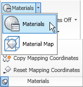 The command most recently selected from the drop-down will become the default for the button. The Materials/Textures drop-down list offers a choice of one of three states: both materials and textures off, materials on but textures off or both materials and textures on (VSMATERIALMODE).
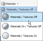 The button displays the current choice. The Material Mapping split button offers another way to use the MATERIALMAP command, this time with a preselected mapping type: Planar, Box, Cylindrical or Spherical.
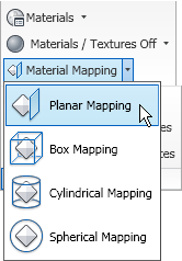 The main button appears to be fixed on "Planar". Selecting the Materials title bar will expand the panel to reveal three additional commands: Attach By Layer (assign materials by the object's layer - MATERIALATTACH), Copy Mapping Coordinates (copy material mapping from one object to another - MATERIALMAP, copY mapping to option) and Reset Mapping Coordinates (reset the mapping to the map defaults - MATERIALMAP, Reset mapping option).
Sun & Location Panel
The Sun & Location Panel contains commands related to including a sun-like light source in your renderings.
 The Sun Status command button allows you to toggle the sun on and off (SUNSTATUS system variable). The Sky button presents itself as a split button, but I was not able to find a way to make this button active. It will display the value of the SKYSTATUS systen variable, which allows you to set whether or not the sky illumination is computed at render time. Changing the value of SKYSTATUS changed the text shown with the button, displaying the current status. It may be that this only becomes active at an appropriate point in the rendering process, which is not something I do on a regular basis. The Set Location button allows you to specify the geographic location of the objects being rendered, so that the sun angles are set correctly. The Date and Time sliders become active when the sun is turned on, and allow you to specify the date and time of the rendering, and the sun angles will be set accordingly. The arrow icon at the far right side of the Sun & Location panel title bar toggles the Sun Properties palette, where you can make addtional sun parameter settings.
Lights Panel
The Lights Panel contains commands related to lighting.
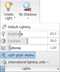 The Create Light split button allows you to place one of three types of lights: Point (POINTLIGHT), Spot (SPOTLIGHT) or Distant (DISTANTLIGHT).
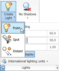 The last type chosen from the drop-down list becomes the command executed by the button; the "Create Light" text remains constant. The Shadows drop-down button allows you to set the type of shadows: none, ground or full (VSSHADOWS command).
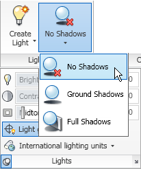 The last option chosen is displayed on the button. Select the Lights panel title bar to expand the panel. The first button on the expanded panel is the Default Lighting button (DEFAULTLIGHTING), which toggles between the default lighting and the lighting placed. The button is highlighted when Default Lighting is active. Three slider controls follow, giving control over Brightness, Contrast and Midtones (RENDEREXPOSURE). The Light glyph display button toggles the display of light glyphs in the drawing (LIGHTGLYPHDISPLAY). This button is also highlighted when active, in this case when the display of light glyphs is enabled. The lighting units drop-down allows you to choose from Generic, American and International lighting units.
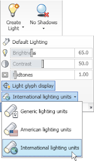 Generic lighting has no units and "standard" lighting. The other two use the units indicated and photometric lighting.
Camera Panel
The Camera Panel contains commands related to cameras.
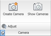 The Create Camera command button runs the CAMERA command, creating a camera object. The Show Cameras command button allows you to toggle the visibility of camera glyphs in the drawing file (CAMERADISPLAY). The button is highlighted when cameras are shown. Select the Camera panel title bar to expand the panel and reveal an additional button, Adjust, which allows you to change the view of a selected camera (AECCAMERAADJUST).
Animations Panel
The Animations Panel contains commands and controls related to animations.
 The Animation Motion Path command button allows you to set camera and/or target paths and make other animation settings in the Motion Path Animation dialog (ANIPATH command). There are four annimation control buttons: play, pause, record and save. The Walk/Fly split button gives you access to the Walk (3DWALK) and Fly (3DFLY) command buttons as well as the Walk and Fly Settings (WALKFLYSETTINGS).
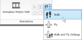 The last item selected becomes the command on the button.
I'm trying to figure out how to apply materials to one side of an object, instead of the whole thing.
ReplyDeleteI tried holding the control key like you would in AutoCAD but that doesn't do anything.
Is it even possible? Thanks.