The Insert tab is the second static (always available) tab provided in the out-of-the-box ACA CUI. The image below and all screen captures in this article are based on the final beta version; it is possible that there could be some changes in the shipping version.

Reference Panel
The Reference Panel contains commands related to reference files.
 The Attach command button allows you to use the Attach command to add an external reference (DWG), image, DWF, DWFx, PDF or DGN to your drawing file. The Clip command button allows you to clip an external reference, image, underlay (DWF, DWFx, PDF or DGN) or a viewport to a user-specified boundary. The Adjust command button allows you to adjust the fade, contrast, brightness and monochrome settings for images and underlays (DWF, DWFx, PDF or DGN). The Underlay Layers command button opens the Underlay Layers dialog, where you can control the visibility of individual layers in an underlay. The Frames command button allows you to choose how image and underlay frames will be seen (and plot).
 Frames can be hidden, displayed and plotted or displayed but not plotted. Setting a Frame setting will overwrite the current values of the IMAGEFRAME, DWFFRAME, PDFFRAME, DGNFRAME and XCLIPFRAME system variables. You can not directly choose the “Frames Vary” option; but changing any of the individual frame variables to something different will reset FRAME to 3 and activate the Frames Vary setting. The Underlays Snap command button allows you to control the ability to snap to geometry in underlays (DWF, DWFx, PDF or DGN).
 It toggles the value of the UOSNAP system variable, which, similar to the FRAME system variable, will overwrite the settings in the DWFOSNAP, PDFOSNAP and DGNOSNAP system variables, making them all either On or Off. You can not directly choose the “Underlay Osnap’s vary” option, but by setting one of the individual variables to a different value will reset UOSNAP to 2 and activate the vary option. The Edit Reference command button (first row in the flyout) runs the REFEDIT command. The Xref Fading command buttons (bottom row in the flyout) allow you to set the amount of fading, using either the slider or the edit box at the right, as well as toggle fading on and off, using the button at the left. (Note: You will not see any apparent change if you use the button at the left if the fading amount is set to 0, since there is no fading to toggle off.) Also note the arrow pointing down and to the right at the right side of the Reference panel title. Selecting that will open the External References palette.
Block Panel
The Block Panel contains command buttons for Multi-View Block and AutoCAD block related commands.
 The Multi-View Block command button runs the MVBlockAdd command; you will need to have at least one Multi-View Block Definition in the current drawing for this to be useful. The Insert Block command button opens the Insert dialog, allowing you to select a block definition in the drawing file or browse to an external drawing file to be inserted as a block. The Create Block command button opens the Block Definition dialog, allowing you to create a new block definition from objects in the drawing. The Edit Block command button allows you to choose a block definition in the current drawing and starts up the Bedit command for that definition. The Block Authoring palettes will open, and the Block Editor contextual tab will appear. The Set Base Point command button runs the Base command, which allows you to specify a point in the current file to act as the insertion base point when the current file is inserted into another file.
Attributes Panel
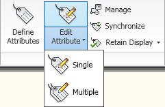
The Attributes Panel contains command buttons related to the creation, editing and display of Attribute Definitions/Attributes.
 The Define Attributes command button runs the Attdef command, allowing you to create attribute definitions for inclusion in a block definition. The Edit Attribute flyout offers two options for editing attribute values. Single runs the EAttEdit command, allowing you to edit the values, text options and properties of the attributes in a single instance of an attributed block. Multiple runs the -AttEdit command, which allows for the editing of attribute values individually or globally.
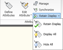
 The Manage command button opens the Block Attribute Manager (BattMan command), which allows you to edit the attribute definitions of all attributed block definitions in the drawing, including the order of the attributes within a block definition, and offers the option to synchronize those changes with existing instances of the block. The Synchronize command button runs the AttSync command, which allows you to synchronize the attributes of all instances of a block with the current block definition (outside of the Block Attribute Manager). The Display flyout offers the ability to control the visibility of attributes.
 The Retain Display option displays attributes according to the visibility assigned to each block attribute. Display all will display all attributes, including hidden attributes. Hide All will hide all attributes, including visible attributes.
Import Panel
The Import Panel has two command buttons. The Import command button initiates the Import command, which allows you to import data files, other than DWG files, and have the data translated into DWG data. The Import File dialog lists file types of Metafile (WMF), ACIS (SAT), 3D Studio (3DS) and Microstation (DGN). The Land XML command button runs the ImportLandXML command, allowing you to import LandXML data and convert it to AEC objects.

Content Panel
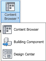
The Content Panel has a single flyout command button, offering three options.
 The Content Browser option opens, surprisingly enough, Content Browser. If you are keeping score at home, this is the second opportunity you have to do so (see the Tools flyout on the Build panel of the Home tab for the first one). Building component allows you to import “building components” that have been “published” from another application (*.adsk files) as a Multi-View Block, Block or, if you are running AutoCAD MEP, as a Multi-View Part (ImportBuildingComponent command). Design Center, as you can probably guess, opens DesignCenter (despite that extra space in the command button name).
Seek Panel
The Seek Panel offers the ability to use the Autodesk Seek feature (also available in DesignCenter), which allows you to search for product specifications and design files over the Internet.

No comments:
Post a Comment
Due to increasing numbers of spam/nonsensical comments, I have now enabled comment moderation. Please allow me some time to review your comment before it appears in the blog.