Here is a quick look at the improved edit-in-place feature for wall endcaps. I must confess that my attempts at using edit-in-place for creating endcaps in previous versions were somewhat half-hearted, as I had become reasonably proficient at creating them by drawing polylines, and the "calculate automatically" feature made creating endcaps from polylines almost painless, for wall styles without stacked components. Perhaps if I had applied myself to the task more diligently, I could have mastered edit-in-place in previous versions, but my few forays generally met with disaster, and I never had time to work out what I was doing incorrectly.
So I approached this feature with low expectations in the 2009 beta, and ended up being very pleased. As previously, I dove in without first trying to read up on the process in the Help - the only "training" was a very short video that was posted, showing the feature in action. I think most people will find the improved feature much more intuitive.
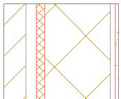
The out-of-the-box CMU-8 Rigid-1.5 Air-2 Brick-4 Furring comes with an endcap style that turns the brick component back into the wall, butting into the rigid insulation, as shown below.

I created a new wall style, based on the CMU-8 Rigid-1.5 Air-2 Brick-4 Furring style, called CMU-12 Rigid-1.5 Air-2 Brick-4 Furring. As you might guess, the only difference is that the CMU component is 1'-0" wide, rather than 8" wide. This will cause the CMU-8 Rigid-1.5 Air-2 Brick-4 Furring (End 1) endcap to do strange things, as it scales things to suit the increased width of the CMU. I could have tried to edit that endcap in place, but chose instead to change the endcap to "Standard" to show just how easy it is to build a similar endcap for the CMU-12 Rigid-1.5 Air-2 Brick-4 Furring wall style "from scratch."
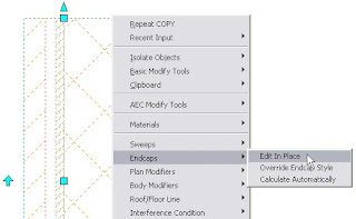
Selecting the wall and right clicking brings up the context menu for walls. Choosing Endcaps > Edit in Place starts the WallEndcapEdit command, and results in a prompt to select a point near the endcap.
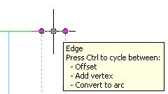
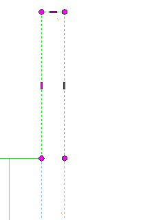
After selecting a point near the top end of my wall instance, the GWB component's endcap was hightlighted, so I chose to start with that component. Vertices are represented by round, magenta grips; edges by rectangular ("hyphen-shaped") grips. Hovering over the edge grip at the top of the GWB component yields a tooltip that indicates the options available for that grip. For our endcap, the default Offset option will do what we need.
 Selecting the grip and offsetting it vertically by four inches gives us the endcap profile we need for this component.
 This same technique was applied to the Stud, CMU and rigid insulation components. Simply select a component to activate its endcap grips.
The Air Space component does not require an offset, as the Brick component will wrap across the top of it. The creation of the Brick component is a two-step process. The first step involves offsetting the component the same four inches vertically the same way as the other offset components were done.
 The second step involves using the edge grip on the right side of the now extended Brick Component, and offsetting that edge by two inches, to bring it to the face of the rigid insulation. Note that you can use object snaps when offsetting components - the edge grips will only offset perpendicular to the face, so you can snap to the endpoint of another component, even if it does not line up with the edge grip in the perpendicular direction.
At this point, having performed a total of six edge grip edits, our endcap is built. Select the save all changes button on the In-Place Edit toolbar to save the changes.
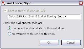
 The Wall Endcap Style dialog will appear, prompting you for a name for your new endcap, and offering the option of making this new endcap the wall style default, or an override for this one location. Since I was building a new endcap for this modified wall style, I chose to make this the default endcap for the wall style.
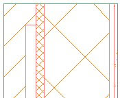
The CMU-12 Rigid-1.5 Air-2 Brick-4 Furring wall instance now sports the new wall endcap style, and the brick returns to the rigid insulation, just like its out-of-the-box cousin.
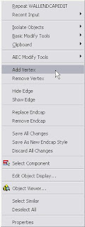
In addition to the grip edit features shown here, the right click context menu available during endcap edit-in-place allows you to add and remove vertices, hide and show edges (hide is the equivalent of drawing a polyline segment with a width, that edge will not be visible in the endcap), replace or remove the endcap, save all changes, save as a new endcap style or discard all changes. The AEC Modify tools are also available to aid in creating more complex profiles. Whether you create a lot of custom endcaps or have met with such frustration with endcaps in the past that you avoid them entirely, the improved edit-in-place of wall endcaps in the 2009 release is a feature you will want to investigate, learn and make use of in the future.
Next Article in the Series: AutoCAD Architecture 2009 - Part 3
No comments:
Post a Comment
Due to increasing numbers of spam/nonsensical comments, I have now enabled comment moderation. Please allow me some time to review your comment before it appears in the blog.