December 17, 2010
Old AUGI Forums to be Restored
As announced by incoming president David Harrington in this thread, the contents of the AUGI forums that were available prior to the change to the new website format are expected to be restored and that the forums section of the website will be using the "old" vBulletin software. This is welcome news on both counts, and will, I hope, result in the restoration of links to threads and ATP class materials made in other posts in this blog, which, as noted here, are currently not valid.
December 11, 2010
Displaying Windows Above the Cut Plane in ACA
Over the years, there have been a number of requests in the Autodesk Discussion Groups and the AUGI Forums on how to get a Window that is above the global cut plane to display in a plan view (Top view direction). There are a number of approaches to this, and which one you should use depends upon how you want to see the Window and whether any particular change has unwanted side effects. For the purposes of this investigation, I am going to assume that the Window in question really is meant to be above the global cut plane and is not simply misplaced vertically in the Wall. I am also assuming that you need to model the Window accurately, that is, draw it to the intended size and place it in the correct vertical position, so that it schedules and/or shows up in generated section/elevations correctly. I will be using imperial units, using the out-of-the-box global cut plane of 3'- 6", but the same display techniques will work in metric units as well. (As always, click on any image to see the image full size. Use the Back button on your browser to return to the article.)
First, you need to decide how a Window above the cut plane should display. If it is a clerestory Window that is well above the cut plane, you may want to indicate the Window in a plan view, but use different graphics than you would for one that is actually cut by the cut plane, so that it is apparent in the plan view that the Window is above the cut plane. On the other hand, you may want one that is not very far above the cut plane to appear just like others that do intersect the cut plane.
Different Graphics
The out-of-the-box Plan Display Representation for Windows includes "Above Cut Plane" components for the Frame, Sash and Glass, but they are turned off. You can have above-cut-plane Windows display when the Plan Display Representation is active by turning on these components and setting the color, linetype and lineweight to suit your needs. This can be done at the Drawing Default, Style or Object level. Drawing Default settings are best edited in the Display Manager. Style-level settings are most easily edited through the Style Manager, or by selecting the object and editing its style. Object-level settings require selecting the object. Because we are making changes to several components, I will be showing the edits using dialogs.* I will also be applying the display settings as Object-level overrides, to allow me to keep a number of different conditions in the same drawing file; you will need to decide whether you should make the changes at the Drawing-Default level (affecting all Windows without a Style- or Object-level override), Style-level (affecting all instances of that Style that do not have an Object-level override) or at the Object-level (affecting just that instance). As shown above, I set an object-level override on the Plan Display Representation of the Window, and turned on the display of the above cut plane components for the frame, sash and glass. I also changed the color, lineweight and plot style to ByBlock and the linetype to HIDDEN2.
If you prefer not to have the Wall Component graphics run through the above-cut-plane Window graphics, you can edit the Plan Display Representation of the Wall, by checking the "Hide Lines Below Openings Above Cut Plane" toggle on the Other tab.
If you would like to have lines at the opening just at the face of the outer component of the Wall, you can turn on the Above Cut Plane component of the Wall. Make certain that the Display Inner Lines Above toggle is unchecked.**
Identical Graphics
If you can find a global cut plane level that will cut through all of your Windows and not adversely affect the display of other objects, the easiest way to get all of your Windows to display identically is to raise the global cut plane to that level.
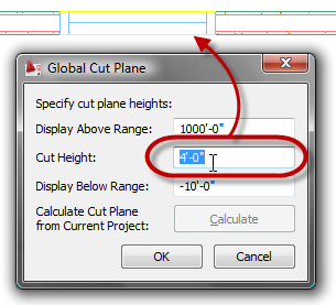
If there is no single global cut plane height that will cut through all Windows, or any such height has unwanted side effects on other objects, you can leave the global cut plane height at your standard height and override the cut plane on Walls. This is done on the Cut Plane tab, by checking the Override Display Configuration Cut Plane toggle, and then entering the desired Cut Plane Height, if you are editing the display settings via dialog, as shown below.
If you are editing on the Display tab of the Properties palette, in the Object Display Properties category, in the Cut Plane subcategory, change the Override cut plane property to Yes and then enter the desired value in the Height property.
If even limiting the cut plane adjustment to Walls with Windows above the global cut plane has unwanted side effects, or you would just prefer not to adjust the cut plane at all, you can still make Windows above the cut plane appear like Windows at the cut plane, by turning on the Frame Above Cut Plane, Sash Above Cut Plane and Glass Above Cut Plane components in the Plan Display Representation for Windows and making the display settings for these components match that of the Frame, Sash and Glass components, respectively.
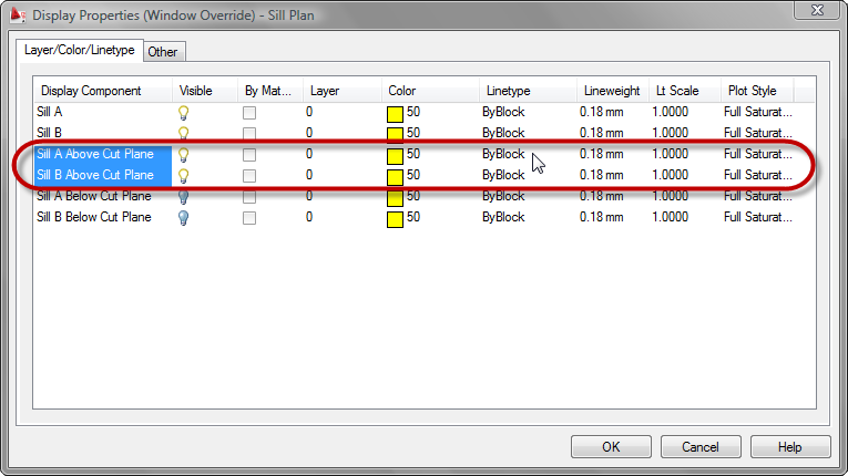
Also turn on the Sill A Above Cut Plane and Sill B Above Cut Plane components and make the display settings match those of the Sill A and Sill B components, respectively.
Finally, edit the display settings of the Plan Display Representation of the Wall, checking the Hide Lines Below Openings Above Cut Plane toggle on the Other tab.
* - You can also make the edits using the Display tab of the Properties palette, but you will have to be able to both select the Window and have the Plan Display Representation active at the same time. To do this, you can either set the Top view direction active with a Display Configuration that uses the Plan Display Representation for the Top view, such as the Medium Detail Display Configuration and temporarily set the Cut Plane high enough to intersect the Window so you can select it, or you can split the Model "tab" into two viewports, setting one to one of the Isometric views in which you can select the Window and setting the other to the Top view direction. Select the Window in the Isometric viewport, then left click in the Top viewport to make it active, and you will have access to the Plan Display Representation and its components on the Display tab of the Properties Palette. You can then select the display level to which the changes are to be applied and then choose/edit each component.
** - The Above Cut Plane component, Display Inner Lines Above toggle and Hide Lines Below Openings Above Cut Plane interact in a similar fashion as the Below Cut Plan component, Display Inner Lines Below toggle and the Hide Lines Below Openings at Cut Plane toggles. See ACA Wall Display Settings at Openings for a detailed description of the interaction.
 (As always, click on any image to see the image full size. Use the Back button on your browser to return to the article.)
First, you need to decide how a Window above the cut plane should display. If it is a clerestory Window that is well above the cut plane, you may want to indicate the Window in a plan view, but use different graphics than you would for one that is actually cut by the cut plane, so that it is apparent in the plan view that the Window is above the cut plane. On the other hand, you may want one that is not very far above the cut plane to appear just like others that do intersect the cut plane.
Different Graphics
The out-of-the-box Plan Display Representation for Windows includes "Above Cut Plane" components for the Frame, Sash and Glass, but they are turned off. You can have above-cut-plane Windows display when the Plan Display Representation is active by turning on these components and setting the color, linetype and lineweight to suit your needs. This can be done at the Drawing Default, Style or Object level. Drawing Default settings are best edited in the Display Manager. Style-level settings are most easily edited through the Style Manager, or by selecting the object and editing its style. Object-level settings require selecting the object. Because we are making changes to several components, I will be showing the edits using dialogs.* I will also be applying the display settings as Object-level overrides, to allow me to keep a number of different conditions in the same drawing file; you will need to decide whether you should make the changes at the Drawing-Default level (affecting all Windows without a Style- or Object-level override), Style-level (affecting all instances of that Style that do not have an Object-level override) or at the Object-level (affecting just that instance).
 As shown above, I set an object-level override on the Plan Display Representation of the Window, and turned on the display of the above cut plane components for the frame, sash and glass. I also changed the color, lineweight and plot style to ByBlock and the linetype to HIDDEN2.
If you prefer not to have the Wall Component graphics run through the above-cut-plane Window graphics, you can edit the Plan Display Representation of the Wall, by checking the "Hide Lines Below Openings Above Cut Plane" toggle on the Other tab.

If you would like to have lines at the opening just at the face of the outer component of the Wall, you can turn on the Above Cut Plane component of the Wall. Make certain that the Display Inner Lines Above toggle is unchecked.**

Identical Graphics
If you can find a global cut plane level that will cut through all of your Windows and not adversely affect the display of other objects, the easiest way to get all of your Windows to display identically is to raise the global cut plane to that level.
If there is no single global cut plane height that will cut through all Windows, or any such height has unwanted side effects on other objects, you can leave the global cut plane height at your standard height and override the cut plane on Walls. This is done on the Cut Plane tab, by checking the Override Display Configuration Cut Plane toggle, and then entering the desired Cut Plane Height, if you are editing the display settings via dialog, as shown below.

If you are editing on the Display tab of the Properties palette, in the Object Display Properties category, in the Cut Plane subcategory, change the Override cut plane property to Yes and then enter the desired value in the Height property.
If even limiting the cut plane adjustment to Walls with Windows above the global cut plane has unwanted side effects, or you would just prefer not to adjust the cut plane at all, you can still make Windows above the cut plane appear like Windows at the cut plane, by turning on the Frame Above Cut Plane, Sash Above Cut Plane and Glass Above Cut Plane components in the Plan Display Representation for Windows and making the display settings for these components match that of the Frame, Sash and Glass components, respectively.

Also turn on the Sill A Above Cut Plane and Sill B Above Cut Plane components and make the display settings match those of the Sill A and Sill B components, respectively.
Finally, edit the display settings of the Plan Display Representation of the Wall, checking the Hide Lines Below Openings Above Cut Plane toggle on the Other tab.

* - You can also make the edits using the Display tab of the Properties palette, but you will have to be able to both select the Window and have the Plan Display Representation active at the same time. To do this, you can either set the Top view direction active with a Display Configuration that uses the Plan Display Representation for the Top view, such as the Medium Detail Display Configuration and temporarily set the Cut Plane high enough to intersect the Window so you can select it, or you can split the Model "tab" into two viewports, setting one to one of the Isometric views in which you can select the Window and setting the other to the Top view direction. Select the Window in the Isometric viewport, then left click in the Top viewport to make it active, and you will have access to the Plan Display Representation and its components on the Display tab of the Properties Palette. You can then select the display level to which the changes are to be applied and then choose/edit each component.

** - The Above Cut Plane component, Display Inner Lines Above toggle and Hide Lines Below Openings Above Cut Plane interact in a similar fashion as the Below Cut Plan component, Display Inner Lines Below toggle and the Hide Lines Below Openings at Cut Plane toggles. See ACA Wall Display Settings at Openings for a detailed description of the interaction.
Previously Posted Links to AUGI Website and Forums
At the beginning of this month, AUGI (Autodesk User Group International) reorganinzed its website and forums. Due to an ongoing "situation" between AUGI and other entities that had been engaged to develop and host the site, all of the forum posts (and, apparently, archived ATP classes, as well) are not currently available.* So any previous links I have posted to threads or other information on the AUGI site are likely to be broken. It is unclear at this time if the old data will be restored, and, if it is, whether the old links will work.
* - See post #61 by Peter Jamtgaard and this blog article by Steve Stafford for two of the less inflamatory explanations of the current situation. Or, if you have the time and the attention span, read through all of the 367 (and counting) posts in this thread in the Revit Architecture Forum and try to figure out what is going on.
* - See post #61 by Peter Jamtgaard and this blog article by Steve Stafford for two of the less inflamatory explanations of the current situation. Or, if you have the time and the attention span, read through all of the 367 (and counting) posts in this thread in the Revit Architecture Forum and try to figure out what is going on.
December 03, 2010
ACA Wall Display Settings at Openings
In preparing a post on the display of Windows that are above the cut plane (coming soon to a blog near you), I decided to investigate the various display options on the Other tab for the Plan Display Represenation for Walls. In particular, it seemed to me that the "Hide Lines Below Openings at Cut Plane" had no actual effect on the Wall's dipslay. It turns out I was wrong, there are conditions under which this toggle does have some effect. I have decided to document my findings here so that I do not have to go through this again in the future. For this article, I will focus on Windows that are cut by the cut plane, the Below Cut Plane component (Layer/Color/Linetype tab), the Display Inner Lines Below toggle on the Other tab and the Hide Lines Below Openings at Cut Plane on the Other tab. In all but the last of the images in this article, all of the Sill Plan components for the Window have been turned off, to avoid any confusion with Wall components. The Above Cut Plane component also is turned off.
The out-of-the-box Plan Display Representation for Walls has the Below Cut Plane component turned on, the Display Inner Lines Below toggle turned off, the Hide Lines Below Openings at Cut Plane toggle is turned on and the Hide Lines Below Openings Above Cut Plane is turned off. The result can be seen in the image below.
The first thing to understand is that if the Below Cut Plane component is turned off, then the settings for Display Inner Lines Below and Hide Lines Below Openings at Cut Plane toggles have no effect, since the Below Cut Plane component is turned off. The result is show below.* With the Below Cut Plane component turned on and the Display Inner Lines Below toggle turned off, the Hide Lines Below Openings at Cut Plane toggle has no effect; the Wall will display just like the out-of-the-box image (first image), with a line at the outer face of the outermost component on each side of the Wall and no inner lines displayed, no matter how the Hide Lines Below Openings at Cut Plane toggle is set.
The next thing to understand is that even though the toggle is called "Display Inner Lines Below", it does in fact refer to inner lines below openings. In the image below, the Below Cut Plane component is on, all of the Boundary and Hatch components are off, the Display Inner Lines Below toggle is turned on and the Hide Lines Below Openings at Cut Plane is turned off. As you can see, lines are drawn at the edges of each component, using the display settings for the Below Cut Plane component, but only below the opening itself. The line at the inner face of the brick component (or outer face of the Air Gap component) appears to break from this and extend a distance into the Wall. This is due to the Wall Endcap having the brick return to the face of insulation component, so the line extends through the depth of the return.
With the Boundary and Hatch components turned back on, the image below shows the effect of having the Below Cut Plane component, Display Inner Lines Below toggle and Hide Inner Lines Below toggle all turned on at the same time.
Strange at it may seem, in order to get all of the lines below turned off without turning off the Below Cut Plane component off, you have to turn the inner lines below on, then hide them. If you do not turn them on, then a line at the outer face of the outer component will remain on, as we saw in the out-of-the-box image above.
Why not just turn off the Below Wall Component? For Walls where each component runs from bottom to top, you could do that. But if you have a Wall that has a projecting component below the cut plane that you want to see in locations where there is no opening and you have a projecting Sill and you do not want to see any Wall lines below the Sill, you will need to leave the Below Wall Component turned on to see the projecting component and then turn on the toggles for both Display Inner Lines Below and Hide Lines Below Openings at Cut Plane to get the desired results (see image below).

I can not say I fully understand why things are set up the way they are, but at least now I have a better understanding of the effects of the various options.
*Oddly enough, you get the same result with the Below Cut Plane component turned on and the Hide Lines Below Openings Above Cut Plane toggled on (with or without the Hide Lines Below Opeings at Cut Plane toggle on or off, provided that Display Inner Lines Below toggle is not turned on). I would not have thought that the Hide Lines Below Openings Above Cut Plane toggle would have any affect on a Window Opening that is at the cut plane, but it does.
The out-of-the-box Plan Display Representation for Walls has the Below Cut Plane component turned on, the Display Inner Lines Below toggle turned off, the Hide Lines Below Openings at Cut Plane toggle is turned on and the Hide Lines Below Openings Above Cut Plane is turned off. The result can be seen in the image below.

The first thing to understand is that if the Below Cut Plane component is turned off, then the settings for Display Inner Lines Below and Hide Lines Below Openings at Cut Plane toggles have no effect, since the Below Cut Plane component is turned off. The result is show below.*
 With the Below Cut Plane component turned on and the Display Inner Lines Below toggle turned off, the Hide Lines Below Openings at Cut Plane toggle has no effect; the Wall will display just like the out-of-the-box image (first image), with a line at the outer face of the outermost component on each side of the Wall and no inner lines displayed, no matter how the Hide Lines Below Openings at Cut Plane toggle is set.
The next thing to understand is that even though the toggle is called "Display Inner Lines Below", it does in fact refer to inner lines below openings. In the image below, the Below Cut Plane component is on, all of the Boundary and Hatch components are off, the Display Inner Lines Below toggle is turned on and the Hide Lines Below Openings at Cut Plane is turned off.
 As you can see, lines are drawn at the edges of each component, using the display settings for the Below Cut Plane component, but only below the opening itself. The line at the inner face of the brick component (or outer face of the Air Gap component) appears to break from this and extend a distance into the Wall. This is due to the Wall Endcap having the brick return to the face of insulation component, so the line extends through the depth of the return.
With the Boundary and Hatch components turned back on, the image below shows the effect of having the Below Cut Plane component, Display Inner Lines Below toggle and Hide Inner Lines Below toggle all turned on at the same time.

Strange at it may seem, in order to get all of the lines below turned off without turning off the Below Cut Plane component off, you have to turn the inner lines below on, then hide them. If you do not turn them on, then a line at the outer face of the outer component will remain on, as we saw in the out-of-the-box image above.
Why not just turn off the Below Wall Component? For Walls where each component runs from bottom to top, you could do that. But if you have a Wall that has a projecting component below the cut plane that you want to see in locations where there is no opening and you have a projecting Sill and you do not want to see any Wall lines below the Sill, you will need to leave the Below Wall Component turned on to see the projecting component and then turn on the toggles for both Display Inner Lines Below and Hide Lines Below Openings at Cut Plane to get the desired results (see image below).

I can not say I fully understand why things are set up the way they are, but at least now I have a better understanding of the effects of the various options.
*Oddly enough, you get the same result with the Below Cut Plane component turned on and the Hide Lines Below Openings Above Cut Plane toggled on (with or without the Hide Lines Below Opeings at Cut Plane toggle on or off, provided that Display Inner Lines Below toggle is not turned on). I would not have thought that the Hide Lines Below Openings Above Cut Plane toggle would have any affect on a Window Opening that is at the cut plane, but it does.
Subscribe to:
Posts (Atom)