Just a reminder for those of you fortunate enough to be registering for AU, I will be teaching a course called Get Fully Equipped in AutoCAD Architecture (AB114-4), which is scheduled for Tuesday, November 27, from 3:00 pm to 4:30 pm in Murano 3203. It is the only AutoCAD Architecture class currently scheduled in that time slot, and I hope to see you there.
Come see a method of creating and scheduling equipment that I have used for several health care projects and which could easily be used on laboratory projects or adapted to any other project type where you need to show equipment or furniture in plan, with identifying tags and then create a schedule to list those items and related data. Equipment not your thing? Then come to see how to analyze a scheduling task and apply the schedule features in AutoCAD Architecture to meet the needs.
Be sure to check out Matt Dillon's Schedule Anything in AutoCAD Architecture or AutoCAD MEP, on Friday, November 30, from 8:00 am - 11:30 am and leave AU 2007 a scheduling pro!
August 22, 2007
August 06, 2007
Details: Welding Symbols Layer Key
Those of you using ADT 2005 or later may have discovered the nifty welding symbols tool on the Basic tool palette in the Detailing tool palette group.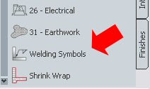 Running this tool opens the Welding Symbols dialog box, which allows you to select from a number of different welding symbol options, and, for those with attributed blocks, provide values for that block's attributes.
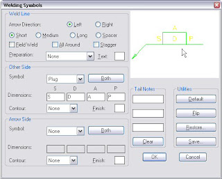
Selecting OK results in the insertion of one or more blocks that form the symbol, and allows you to create one or more leaders to point to the place(s) where the weld symbol applies.
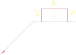
The source file for the "WPLG" plug weld block shown above is WPLG.dwg, which, like the other welding symbol blocks, can be found in the C:\Program Files\AutoCAD Architecture 2008\Welding folder if the default file locations were used on installation. The polyline that forms the linework for this block is drawn on Layer 0, with ByLayer properties, so it will inherit the layer, color, linetype and lineweight of the layer on which the block is placed. The attributes are defined on a layer called WELDTEXT, with ByLayer properties. The way Details blocks work is if the layer name on which an object is drawn matches a Layer Key name in the current Layer Key Style, then that object, when inserted into the drawing, will be put on the layer assigned to that Layer Key.
The overall welding symbol is assigned to the ANNOBJ Layer Key, so the block(s) and leaders are placed on the A-Anno-Note layer for the out-of-the-box AIA (256 Color) Layer Key Style, with no overrides set. Unfortunately, the AIA (256 Color) Layer Key Style that has shipped with the program since ADT 2005 does not contain a Layer Key called WELDTEXT. Nor do any of the other out-of-the-box Layer Key Styles that I have examined.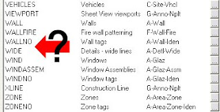 Because of this, ADT/ACD-A simply keeps the attributes on the WELDTEXT layer, as defined in the source file. (As always, click on any "reduced size" image file to see the image full size.)
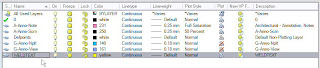
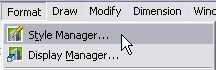
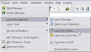
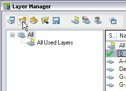
Fortunately, adding a Layer Key is quite easy, so if you want to get the attributes of your welding symbols on a layer other than WELDTEXT, add a WELDTEXT Layer Key and specify the layer name and properties of the layer on which you want the attributes to be placed. You can edit a Layer Key Style through the Style Manager (Format > Style Manager..., then look in the Multi-Purpose Object folder -OR- Format > Layer Management > Layer Key Styles... from the pulldown menus) or by opening the Layer Manager and selecting the Layer Key Styles button (second from left) on the toolbar at the top of the dialog.
Once you have the Style Manager open and have found and expanded the Layer Key Styles category in the Multi-Purpose Objects folder, select the name of the Layer Key Style you use in the left pane, and then select the Keys tab in the right pane. Left click on the New button at the lower right corner.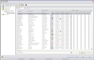
In the Name dialog, type WELDTEXT in the edit box and select OK to create a new Layer Key of that name.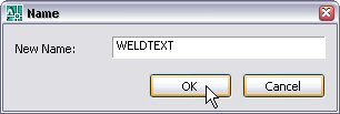
Enter a description for the Layer Key, and add a layer name (use the ellipsis button to build a layer name from predefined components in your Layer Standard) and set the layer parameters. I chose color 182, a dark purple, for contrast with the default yellow color. You may wish to choose a different color.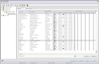 One curious "feature" when adding a new Layer Key that I have never understood is that the Allow Overrides toggles for the new Layer Key are not active. You will need to "Apply" your changes, then reselect the name of your Layer Key Style in the left pane. Now the Allow Overrides toggles are active, and you can, if you wish, check them to allow Layer Key Overrides to be applied to the various components of the layer name.
Once you have tested the new Layer Key, you will want to copy the revised Layer Key Style to your auto-import file. You can find the name and location of this file on the Layering tab of the Drawing Set dialog. If you have the "always import" toggle on that tab checked, the updated Layer Key Style will be imported when opening existing drawings and using any feature that involves a Layer Key. If you do not have the "always import" toggle checked, you will need to update the Layer Key Style in any existing drawings manually. I would recommend having the "always import" toggle checked; if you do not, at the very least you should make certain that your template files do not have a Layer Key Style defined within them, so that new files will always inherit the latest version of the Layer Key Style from the auto-import file.
Note also that in any existing files in which you have already placed a particular attributed welding symbol block, the WELDTEXT layer is already built into the block definition, and you would need to redefine the block manually, then use ATTSYNC to update the attributes of the previously existing instances of that block. But for new drawings, or for blocks not already defined, that have the new Layer Key Style with the WELDTEXT Layer Key, the attributes will now be placed on the layer assigned to the WELDTEXT Layer Key.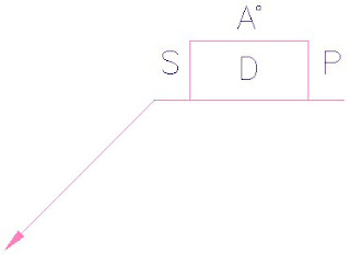
 Running this tool opens the Welding Symbols dialog box, which allows you to select from a number of different welding symbol options, and, for those with attributed blocks, provide values for that block's attributes.
Selecting OK results in the insertion of one or more blocks that form the symbol, and allows you to create one or more leaders to point to the place(s) where the weld symbol applies.

The source file for the "WPLG" plug weld block shown above is WPLG.dwg, which, like the other welding symbol blocks, can be found in the C:\Program Files\AutoCAD Architecture 2008\Welding folder if the default file locations were used on installation. The polyline that forms the linework for this block is drawn on Layer 0, with ByLayer properties, so it will inherit the layer, color, linetype and lineweight of the layer on which the block is placed. The attributes are defined on a layer called WELDTEXT, with ByLayer properties. The way Details blocks work is if the layer name on which an object is drawn matches a Layer Key name in the current Layer Key Style, then that object, when inserted into the drawing, will be put on the layer assigned to that Layer Key.
The overall welding symbol is assigned to the ANNOBJ Layer Key, so the block(s) and leaders are placed on the A-Anno-Note layer for the out-of-the-box AIA (256 Color) Layer Key Style, with no overrides set. Unfortunately, the AIA (256 Color) Layer Key Style that has shipped with the program since ADT 2005 does not contain a Layer Key called WELDTEXT. Nor do any of the other out-of-the-box Layer Key Styles that I have examined.
 Because of this, ADT/ACD-A simply keeps the attributes on the WELDTEXT layer, as defined in the source file. (As always, click on any "reduced size" image file to see the image full size.)
Fortunately, adding a Layer Key is quite easy, so if you want to get the attributes of your welding symbols on a layer other than WELDTEXT, add a WELDTEXT Layer Key and specify the layer name and properties of the layer on which you want the attributes to be placed. You can edit a Layer Key Style through the Style Manager (Format > Style Manager..., then look in the Multi-Purpose Object folder -OR- Format > Layer Management > Layer Key Styles... from the pulldown menus) or by opening the Layer Manager and selecting the Layer Key Styles button (second from left) on the toolbar at the top of the dialog.


Once you have the Style Manager open and have found and expanded the Layer Key Styles category in the Multi-Purpose Objects folder, select the name of the Layer Key Style you use in the left pane, and then select the Keys tab in the right pane. Left click on the New button at the lower right corner.

In the Name dialog, type WELDTEXT in the edit box and select OK to create a new Layer Key of that name.

Enter a description for the Layer Key, and add a layer name (use the ellipsis button to build a layer name from predefined components in your Layer Standard) and set the layer parameters. I chose color 182, a dark purple, for contrast with the default yellow color. You may wish to choose a different color.
 One curious "feature" when adding a new Layer Key that I have never understood is that the Allow Overrides toggles for the new Layer Key are not active. You will need to "Apply" your changes, then reselect the name of your Layer Key Style in the left pane. Now the Allow Overrides toggles are active, and you can, if you wish, check them to allow Layer Key Overrides to be applied to the various components of the layer name.
Once you have tested the new Layer Key, you will want to copy the revised Layer Key Style to your auto-import file. You can find the name and location of this file on the Layering tab of the Drawing Set dialog. If you have the "always import" toggle on that tab checked, the updated Layer Key Style will be imported when opening existing drawings and using any feature that involves a Layer Key. If you do not have the "always import" toggle checked, you will need to update the Layer Key Style in any existing drawings manually. I would recommend having the "always import" toggle checked; if you do not, at the very least you should make certain that your template files do not have a Layer Key Style defined within them, so that new files will always inherit the latest version of the Layer Key Style from the auto-import file.
Note also that in any existing files in which you have already placed a particular attributed welding symbol block, the WELDTEXT layer is already built into the block definition, and you would need to redefine the block manually, then use ATTSYNC to update the attributes of the previously existing instances of that block. But for new drawings, or for blocks not already defined, that have the new Layer Key Style with the WELDTEXT Layer Key, the attributes will now be placed on the layer assigned to the WELDTEXT Layer Key.

August 05, 2007
Command Tool: Open a Specific File
If you have bought into the tool palette workflow in AutoCAD® Architecture/Autodesk® Architectural Desktop, you may find yourself wanting to move other customizations that you formerly might have put on a toolbar on a tool palette. Fortunately, there is a tool type just for this occasion, the Command Tool. You can find a "blank" version of the Command Tool in the Stock Tool Catalog that ships with ACD-A/ADT, in the Helper Tools category.
A post in the AutoCAD Architecture 2008 Discussion Group asked if there was a way to have a tool on a tool palette open a specific file. After a little confusion over exactly was wanted got cleared up, I noted that while I was unable to get either the OPEN or NEW commands to work directly in a Command Tool to either open a specific file or start a new file with a specific template without the user interacting with the "Select File" or "Select template" dialogs, I was able to use a script file to run the NEW command at the Command Line and to get the desired template file entered onto the Command Line, only requiring the end user to press the Enter key. I thought I tried addiing a space to the end of the script to force the value to be accepted and end the command, and it did not work, but I was in a bit of a hurry and may have not properly edited and saved the script file. I have taken a second look at this, in ACD-A 2008 and in ADT 2005, and was able to get both the OPEN and NEW commands to fully execute by running a script file from a tool palette tool. While opening most files is probably best done by the user directly with the OPEN command (or through Project Navigator, if you are using that), there may be a few "source files" to which you would like to have direct access, without a lot of navigation in the "Select File" dialog. If you are putting together a palette of tools related to a specific task that requires starting a new drawing with a specific template file - especially if it is not your typical default file - then the New File tool may be of use to you.
The first thing you will need is the script file. Script files, for those who do not know, are plain text files that represent the keystrokes you would type at the Command Line. Notepad is a good choice for creating and editing script files, as you do not have to worry that the saved files will have any of the extraneous formatting information that a word processor can put into a file. The SCRIPT command is then used to open a run a script file, feeding the text in the script file to the Command Line. Many commands, that would normally open a dialog box for user input will run a Command Line version when invoked from a script, even when FILEDIA is set to 1 and including those, such as OPEN and NEW, that no longer have a Command Line version (command name preceded by a "-"). For an OPEN tool, you will need to know the file name and the path where the file will be stored. For a NEW tool, you will need to know the file name and path of the template file you wish to use. The text of the script files I created when testing this tonight follow:
OPEN Tool
NEW Tool
Two things to note in the samples above. First, there is a single space at the end of the second line; that space acts as the "Enter" after the file name is passed to the OPEN or NEW command, ending the command input and executing the command. Second, the path for the drawing file or template file has forward slashes, rather than the ususal backslashes, to separate folder names. Script files will interpret a backward slash as a pause for user input. The forward slashes will be interpreted correctly; just be aware that you can not simply cut and paste the path from Windows Explorer to the script. The script file then needs to be saved to a location to which everyone running the tool has access.
At this point, I also quickly created two rather crude BMP files to serve as the tool images, by "stealing" the graphics for the OPEN and NEW toolbar buttons on the Standard toolbar. If I had to look at these tools on a regular basis, I probably would have spent a little more time and made much nicer images. You could also just live with the default image for a Command Tool, a white square.
After creating a new tool palette in my current workspace on which to create the new tools (setting an existing, editable tool palette current also works), I opened the Content Browser, found and opened the Stock Tool Catalog, navigated to the Helper Tools category...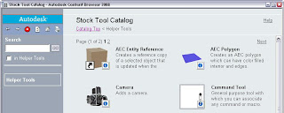 ...and i-dropped the Command Tool onto the tool palette.
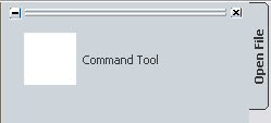
I right clicked on that tool and made a copy, so I would have two command tools, one for OPEN and one for NEW. I then right clicked on the tool that was to run the OPEN script and chose Properties... from the context menu. I gave the tool a name and a decription. The description is displayed in the tool tip when you hover over a tool, so providing a meaningful description can be helpful to those using the tool. I chose to indicate the command (Open) and the full path and file name of the file to be opened. I then right clicked in the Image area, and chose Specify Image... from the context menu (the only choice). I navigated to the location where I had saved the image file for the Open command and selected that file. The command string entered can be seen in the image below; the SCRIPT command is run, and the script file, with full path, completes the command string. Once again, forward slashes are used to separate folders in the path. Select OK to close the Command dialog and OK again to save and close the changes made to the tool's properties.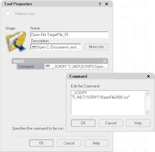
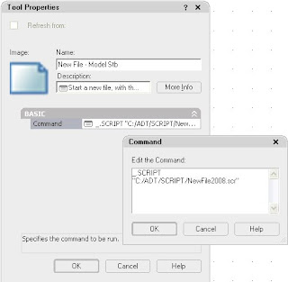
Creating the tool for the NEW script followed the same procedure as noted above for the OPEN tool; an image showing the properties dialog with the command string for the NEW tool is shown below.
All that remains is to test the tools (you may want to test the script files manually first, to be certain they work, before testing the tools). Once you are satisfied they work, you can share them with others through the Content Browser, like any other tool.

A post in the AutoCAD Architecture 2008 Discussion Group asked if there was a way to have a tool on a tool palette open a specific file. After a little confusion over exactly was wanted got cleared up, I noted that while I was unable to get either the OPEN or NEW commands to work directly in a Command Tool to either open a specific file or start a new file with a specific template without the user interacting with the "Select File" or "Select template" dialogs, I was able to use a script file to run the NEW command at the Command Line and to get the desired template file entered onto the Command Line, only requiring the end user to press the Enter key. I thought I tried addiing a space to the end of the script to force the value to be accepted and end the command, and it did not work, but I was in a bit of a hurry and may have not properly edited and saved the script file. I have taken a second look at this, in ACD-A 2008 and in ADT 2005, and was able to get both the OPEN and NEW commands to fully execute by running a script file from a tool palette tool. While opening most files is probably best done by the user directly with the OPEN command (or through Project Navigator, if you are using that), there may be a few "source files" to which you would like to have direct access, without a lot of navigation in the "Select File" dialog. If you are putting together a palette of tools related to a specific task that requires starting a new drawing with a specific template file - especially if it is not your typical default file - then the New File tool may be of use to you.
The first thing you will need is the script file. Script files, for those who do not know, are plain text files that represent the keystrokes you would type at the Command Line. Notepad is a good choice for creating and editing script files, as you do not have to worry that the saved files will have any of the extraneous formatting information that a word processor can put into a file. The SCRIPT command is then used to open a run a script file, feeding the text in the script file to the Command Line. Many commands, that would normally open a dialog box for user input will run a Command Line version when invoked from a script, even when FILEDIA is set to 1 and including those, such as OPEN and NEW, that no longer have a Command Line version (command name preceded by a "-"). For an OPEN tool, you will need to know the file name and the path where the file will be stored. For a NEW tool, you will need to know the file name and path of the template file you wish to use. The text of the script files I created when testing this tonight follow:
OPEN Tool
_.OPEN
"C:/Documents and Settings/David Koch/My Documents/The Architect's Desktop Blog/Tool Palette Tool To Open File/TargetFile_01.dwg"
NEW Tool
_.NEW
"C:/Documents and Settings/All Users/Application Data/Autodesk/ACD-A 2008/enu/Template/Aec Model (Imperial Stb).dwt"
Two things to note in the samples above. First, there is a single space at the end of the second line; that space acts as the "Enter" after the file name is passed to the OPEN or NEW command, ending the command input and executing the command. Second, the path for the drawing file or template file has forward slashes, rather than the ususal backslashes, to separate folder names. Script files will interpret a backward slash as a pause for user input. The forward slashes will be interpreted correctly; just be aware that you can not simply cut and paste the path from Windows Explorer to the script. The script file then needs to be saved to a location to which everyone running the tool has access.
At this point, I also quickly created two rather crude BMP files to serve as the tool images, by "stealing" the graphics for the OPEN and NEW toolbar buttons on the Standard toolbar. If I had to look at these tools on a regular basis, I probably would have spent a little more time and made much nicer images. You could also just live with the default image for a Command Tool, a white square.
After creating a new tool palette in my current workspace on which to create the new tools (setting an existing, editable tool palette current also works), I opened the Content Browser, found and opened the Stock Tool Catalog, navigated to the Helper Tools category...
 ...and i-dropped the Command Tool onto the tool palette.
I right clicked on that tool and made a copy, so I would have two command tools, one for OPEN and one for NEW. I then right clicked on the tool that was to run the OPEN script and chose Properties... from the context menu. I gave the tool a name and a decription. The description is displayed in the tool tip when you hover over a tool, so providing a meaningful description can be helpful to those using the tool. I chose to indicate the command (Open) and the full path and file name of the file to be opened. I then right clicked in the Image area, and chose Specify Image... from the context menu (the only choice). I navigated to the location where I had saved the image file for the Open command and selected that file. The command string entered can be seen in the image below; the SCRIPT command is run, and the script file, with full path, completes the command string. Once again, forward slashes are used to separate folders in the path. Select OK to close the Command dialog and OK again to save and close the changes made to the tool's properties.

Creating the tool for the NEW script followed the same procedure as noted above for the OPEN tool; an image showing the properties dialog with the command string for the NEW tool is shown below.

All that remains is to test the tools (you may want to test the script files manually first, to be certain they work, before testing the tools). Once you are satisfied they work, you can share them with others through the Content Browser, like any other tool.
Subscribe to:
Posts (Atom)