March 31, 2006

Enhanced Property Data Features in ADT 2007, Part 4

A new object type has been added to ADT 2007, the List Definition. If you used the Area object in previous releases of ADT, you may be familiar with Name Definitions, which allowed you to create a list of names that could be used for areas attached to an area group, with a specific name selected from a dropdown list in the Properties palette. The new List Definition object takes over that role in ADT 2007 and expands it by allowing you to assign a List Defintion to a Manual property in a Property Set Defintion. This will allow you to offer your users the long-requested ability to choose a value from a drop-down list, rather than having to type the values in manaully each time, introducing the probability of typographic errors.

List Definition objects are created and edited in the Style Manager, and can be found under the Multi-Purpose Objects folder. [Name Definitions used to be under the Documentation Objects folder.] The General tab offers the usual opportunity to edit the Name and Description of your List Definition. The Applies To tab, shown below, allows you to specify to which object types the list will apply: Manual Property Definitions, Space Names [the 2007 equivalent of Area names - you have heard that Spaces, Areas and ABS Spaces have all merged into one object in 2007, haven't you?] and/or Zone Names [the 2007 equivalent to Area Groups and ABS Zones]. Note that unlike previous versions of ADT, the default initial state of the Applies To tab is to have all choices NOT selected. This holds true when creating other styles or defintions with an Applies To tab, like Property Set Defintions and Schedule Table Styles. The Select All and Clear All buttons are still there [but not shown in the image]. This is a welcome change, as most times you will want the new style/defintion to apply to only a few of the choices, at most. You no longer have to hit Clear All first, then make your choices.

You create the actual list entries on the Items tab. The Add and Remove buttons allow you to add new entries and remove existing entries, respectively. When checked, the "Allow individual property values to vary from this list" toggle permits the user to manually type in a value, in addition to selecting it from the list.

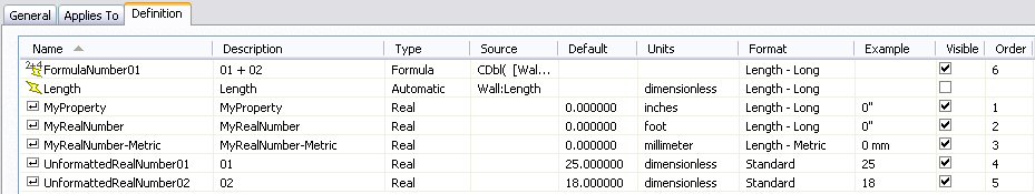
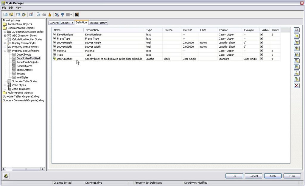
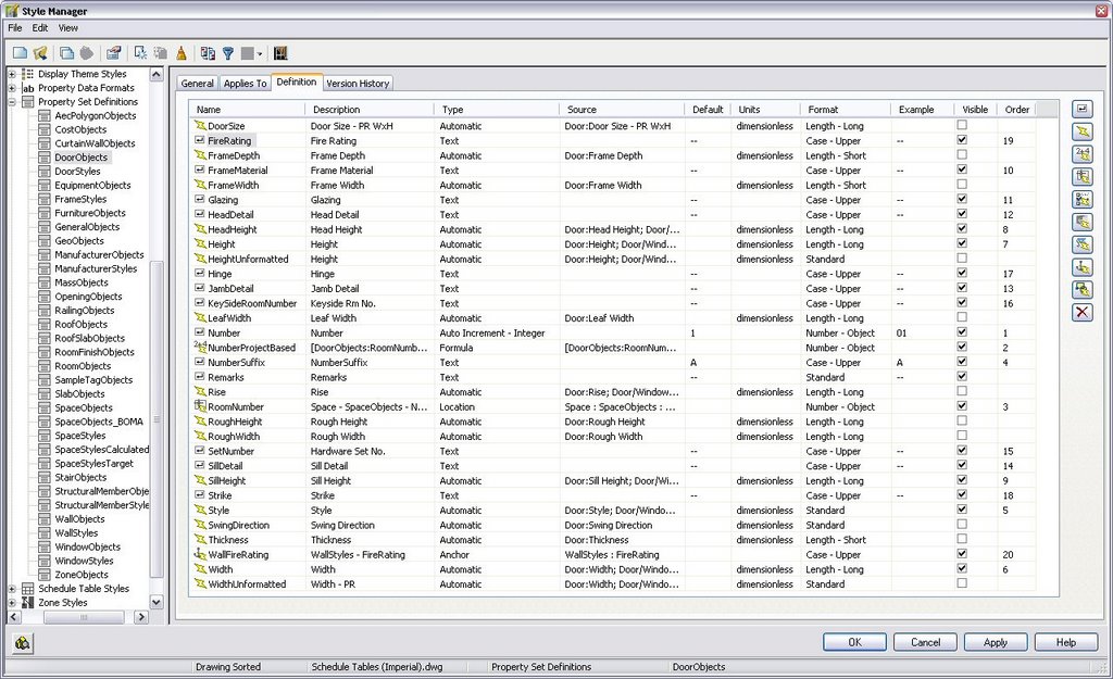
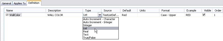
Once you have a List Defintion that applies to Manual Property Defintions set up and populated with values, it is ready to be assigned to a Manual property. To do so, create the Manual property or edit an existing one, and set/change the property Type to "List" by selecting it from the drop down list as shown below. If you have more than one List Defintion in your drawing file, you can specify which list to use in the Source column, set a default value in the Default column, apply a Property Data Format in the Format column, look at the effect of the Property Data Format in the Example column and set the visibility and order as noted in Part 1 of this series.

When you attach the Property Set containing your new List-type Manual property to an object [or a style] of the type to which the Property Set applies, you can set the value for the new manual property. Do this by selecting a value from the dropdown list in the Edit Property Set Data dialog......or the Properties palette.

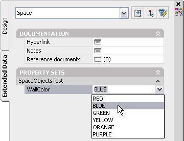
If you checked the toggle to allow values to vary from the list, you can also type in a value not on the list.

Three cheers for the ADT Development Team in crossing off another wish list item.

March 24, 2006

Enhanced Property Data Features in ADT 2007, Part 3

Here is another new feature related to property data, coming your way in the soon to be released ADT 2007. You can now specify a Unit Type when setting up a Property Data Format, so that ADT "knows" what type of data to expect for that property. Please note that the Unit Types ONLY apply to manual properties, and only those set to the "Real" type. Auto Increment - Character, Auto Increment - Integer, Integer, Text and True/False types of manual properties do not make use of this new feature. You set the Unit Type in the Real Numbers area of the Formatting tab when editing the Property Data Format, as seen in the image below. The image also displays the list of different Unit Types available.


Each Unit Type then has an associated list of Units relevant to that type. You set a "default" Unit value in the PDF, and this will be used when first assigning a PDF to a new property. Once the property has a value assigned, that value "sticks" when changing to a new PDF, rather than changing to the default value of the new PDF, if the Unit Type is the same for both old and new PDFs. The Units available for the Length Unit Type can be seen in the image below.


Once you assign a PDF to a Real manual property, you can change the Units to any of those available for the assigned Unit Type in the Units column on the Definition tab, when editing a Property Set Defintion. Simply click on the current value to activate a dropdown list of available values. I will repeat that this only applies to Real manual properties; formula properties will be blank in the Units column, and the Automatic properties will list "dimensionless" but not offer any other choices in a dropdown list, as shown in the image below.


The final image shows the Extended Data tab for a wall that has the Property Set shown above attached. MyProperty and MyRealNumber both have the Length - Long Property Data Format attached, which uses the Architectural Unit Format and the Length Unit Type. MyProperty uses the default inches for the Unit, while MyRealNumber was changed to feet. The value typed into MyProperty was 38.75; the value typed into MyRealNumber was 12. These display as 3'-2 3/4" and 12'-0", respectively.


Note that if you want to use a number for mathematical purposes in a formula, you will want to stay away from the Architectural and Engineering Unit Formats, which convert numbers to imperial feet and inches format, which will be interpreted as a string, as well as avoiding text prefixes or suffixes. But you CAN use the Decimal Unit Format and assign a Unit Type and Units, such as Length and Inches, without creating a string. You can also choose to set the Unit Type to "(none)", as the out-of-the-box Standard Property Data Format does. This shows in the Units column of a Property Set Defintion as "dimensionless".

Also note that the Unit Type/Units settings affect the way the numbers input are interpreted, but not necessarily the way they are displayed. If your drawing units are inches, but you set up a Real manual property, in Decimal Unit Format, with units of Feet, when you enter the number, you are entering the value in feet, but after you hit return, the value will be displayed in inches [and the value will be twelve times bigger than you entered, since there are twelve inches in a foot]. Unless you have a specific case where you want to enter metric values, but display them in feet and inches, I would not recommend mixing the Architectural or Engineering Unit Format with a Length Unit Type and one of the metric units. I tried that, using Architectural with millimeters, and an entry of 1000 [mm] was displayed as 3'-3 3/8".

March 21, 2006

Enhanced Property Data Features in ADT 2007, Part 2

Here are two more Property Data features to look forward to in ADT 2007. Two new property types have been added:
- Anchor properties
- Graphic properties

Anchor properties allow you to read in property data into an object from another object to which the first object is anchored. For example, a door anchored to a wall can read property data from the wall, such as the fire-resistance rating of the wall. This was possible in ADT 2004-2006, by using some VBScript code in a formula property - see this thread in the ADT 2006 Discussion Group if you are interested - but the code was version-specific [different for 2004, 2005 and 2006], and for the 2004 and 2005 versions, would not work across external references. The new anchor property does away with all of the formula coding, and lets you choose a property from an existing property set just like you do for location properties, as shown in the Anchor Property Definition dialog below:


Graphic properties allow you to add graphics to your schedule table, by specifying either a block or an image to be displayed in the table. When creating a graphic property, you will be asked to provide a default block or image, but when you attach the property set to a style or object, you can accept the default or choose another, specific to that style/object. The layer key chosen will be applied to the blocks; if you freeze that layer, the blocks will also be frozen [and disappear].

As an example, I made a copy of the out-of-the-box "DoorStyles" Property Set Definition, and added a graphic property, "DoorGraphics". I made three plan-view blocks for doors, one each for a single door, double door and double egress door. The block graphics were all drawn on layer 0, with ByBlock attributes, so they will pick up the layer attributes of the layer associated with the chosen layer key - DOOR. I set the "Door - Single" block as the default block.

In my test file, I added a few doors of each type, then edited the door styles and added my "DoorStyles-Modified" Property Set to each, selecting the appropriate block for the double and double egress doors and accepting the default for the single doors. The Graphic Property dialog that appears is identical to the Graphic Property Definition dialog, except for the name. I then modified a copy of the out-of-the-box "Door Schedule" Schedule Table Style and added a new column referencing the DoorStyles-Modified:DoorGraphics property. The image below shows the part of the resultant door schedule. The graphics appear on the A-Door layer [which gets created, if necessary]. Note that the blocks are scaled to fit the height and width of the column, so the double egress block appears "smaller" than the other two, even though the doors swing graphics are copies, because the overall block is taller.

Also note that the blocks must exist in the drawing in order to be able to assign them to a style/object and for them to appear in the schedule. So if you create the schedule in a file that uses external references [Xrefs] in the file with the schedule, or references an external file, you will not get the images until you manually copy the blocks to the file with the schedule. If you assign a block to a graphic property in a style-based Property Set, as I did, and then use Style Manager to copy the style to a new drawing, the block name will go along with the copied style, but the block definition does not, and must be manually copied if you want to place an instance of the schedule in that file.

March 11, 2006

Enhanced Property Data Features in ADT 2007, Part 1

My apologies for my month-long gap in posts, but I spent all my "free" time this past month racing against a deadline at work [with a break last Saturday for my mother-in-law's 90th birthday party], and was not able to jump in when the embargo on the 2007 products was lifted. I will try to make up for that in the coming weeks.

Here is a quick look at two new features added to Property Sets. As you can see in the screen capture of the out-of-the-box DoorObjects Property Set, there are two new columns at the right of the Definition tab: Visibility and Order.


Visibility lets you tell ADT whether a property should be displayed on the Extended Data tab of the Properties Palette or in the Edit Property Set Data dialog that appears when you tag an object. Notice that a number of the automatic properties are not checked - these will not be visible when editing the properties. This can be especially effective for automatic properties, that you can not edit anyway.

The Order column lets you decide the order in which the properties that are visible appear on the the Extended Data tab of the Properties Palette and the Edit Property Set Data dialog. You could choose to group similar properties, or put all of the manual properties together at the top - in a logical order of data entry, rather than alphabetical order, making it easier for the user to enter the data needed.